ENG_822033.xml
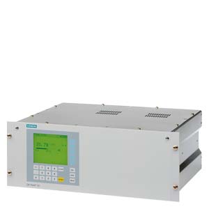
- 19" rack unit with 4 U for installation
- In hinged frame
- In cabinets with or without telescopic rails
- Front plate can be swung down for servicing purposes (laptop connection)
- Gas connections for sample gas inlet and outlet; pipe diameter 6 mm or ¼"
- Gas and electrical connections at the rear of the device
Display and operator panel
- Large LCD field for simultaneous display of
- Measured value
- Status bar
- Measuring ranges
- Contrast of LCD panel adjustable using menu
- Permanent LED backlighting
- Washable membrane keyboard with five softkeys
- Menu-driven operation for parameterization, test functions, adjustment
- User help in plain text
- Graphic display of concentration trend; programmable time intervals
- Bilingual operating software German/English, English/Spanish, French/English, Spanish/English, Italian/English
Inputs and outputs
- One analog output per medium (from 0, 2, 4 to 20 mA; NAMUR parameterizable)
- Six digital inputs freely configurable (e.g. for measuring range switchover, processing of external signals from sample preparation)
- Six relay outputs freely configurable (failure, maintenance demanded, maintenance switch, limit alarm, external solenoid valves)
- Two analog inputs configurable (e.g. correction of cross-interference, external pressure sensor)
- Expansion by eight additional digital inputs and eight additional relay outputs for autocalibration with up to four calibration gases
Communication
RS 485 present in basic unit (connection from the rear).
Options
- RS 485/RS 232 converter
- RS 485/Ethernet converter
- RS 485/USB converter
- Connection to networks via PROFIBUS DP/PA interface
- SIPROM GA software as service and maintenance tool

G_PA10_XX_00008
OXYMAT 61, membrane keyboard and graphic display
Designs – Parts wetted by sample gas, standard
|
Gas path
|
19" rack unit
|
|
With hoses
|
Bushing
|
Stainless steel. Mat. no. 1.4571
|
|
Hose
|
FKM (Viton)
|
|
Sample chamber
|
Stainless steel. Mat. no. 1.4571
|
|
Fittings for sample chamber
|
Stainless steel. Mat. no. 1.4571
|
|
Restrictor
|
PTFE (Teflon)
|
|
O-rings
|
FKM (Viton)
|
|
Hose coupling
|
Polyamide 6
|
|
Options
|
|
Flow indicator
|
Measuring tube
Variable area
Suspension boundary
Angle units
|
Duran glass
Duran glass, black
PTFE (Teflon)
FKM (Viton)
|
|
Pressure switch
|
Diaphragm
Enclosure
|
FKM (Viton)
PA 6.3 T
|
Gas path

G_PA10_XX_00033
Gas path OXYMAT 61 with integrated reference gas pump (connection for 1 100 hPa, absolute)

G_PA10_XX_00034
Gas path OXYMAT 61 with reference gas connection 3 000 to 5 000 hPa, absolute
|
Legend for the gas path figures
|
|
1
|
Sample gas inlet
|
8
|
Pressure switch in sample gas path (option)
|
|
2
|
Sample gas outlet
|
9
|
Restrictor in reference gas channel (outlet)
|
|
3
|
Not used
|
10
|
Pressure switch for reference gas monitoring
|
|
4
|
Reference gas inlet
|
11
|
Pump
|
|
5
|
Restrictor in reference gas inlet
|
12
|
Filter
|
|
6
|
O2 physical system
|
13
|
Flow indicator in sample gas path (option)
|
|
7
|
Restrictor in sample gas path
|
14
|
Pressure sensor
|
ENG_822032.xml
In contrast to almost all other gases, oxygen is paramagnetic. This property is utilized as the measuring principle by the OXYMAT 61 gas analyzers.
Oxygen molecules in an inhomogeneous magnetic field are drawn in the direction of increased field strength due to their paramagnetism. When two gases with different oxygen contents meet in a magnetic field, a pressure difference is produced between them.
In the case of OXYMAT 61, one gas (1) is a reference gas (N2, O2 or air), the other is the sample gas (5). The reference gas is introduced into the sample chamber (6) through two channels (3). One of these reference gas streams meets the sample gas within the area of a magnetic field (7). Because the two channels are connected, the pressure, which is proportional to the oxygen content, causes a cross flow. This flow is converted into an electric signal by a microflow sensor (4).
The microflow sensor consists of two nickel-plated grids heated to approximately 120 °C, which, along with two supplementary resistors, form a Wheatstone bridge. The pulsating flow results in a change in the resistance of the Ni grids. This leads to an offset in the bridge which is dependent on the oxygen concentration of the sample gas.
Because the microflow sensor is located in the reference gas stream, the measurement is not influenced by the thermal conductivity, the specific heat or the internal friction of the sample gas. This also provides a high degree of corrosion resistance because the microflow sensor is not exposed to the direct influence of the sample gas.
By using a magnetic field with alternating strength (8), the effect of the background flow in the microflow sensor is not detected, and the measurement is thus independent of the sample chamber position as well as the gas analyzer's operating position.
The sample chamber is directly in the sample path and has a small volume, and the microflow sensor is a low-lag sensor. This results in a very short response time for the OXYMAT 61.
Note
The sample gases must be fed into the analyzers free of dust. Condensation in the sample chambers must be prevented. Therefore, gas modified for the measuring tasks is necessary in most application cases.

G_PA10_XX_00011
OXYMAT 61, mode of operation
ENG_822030.xml
Main features
- Four measuring ranges which can be freely configured, even with suppressed zero point; all measuring ranges are linear
- Galvanically isolated measured value output 0/2/4 through to 20 mA (including inverted)
- Choice of automatic or manual measurement range switchover; remote switching is also possible
- Storage of measured values possible during calibration
- Wide range of selectable time constants (static/dynamic noise damping); i.e. the response time of the device can be adapted to the respective measuring task
- Easy handling thanks to menu-driven operation
- Low long-term drift
- Two control levels with separate authorization codes for the prevention of accidental and unauthorized operator interventions
- Automatic measuring range calibration parameterizable
- Operation based on NAMUR recommendation
- Monitoring of sample gas (option)
- Custom-made device designs, such as:
- Customer acceptance
- TAG plates
- Drift recording
- Simple handling using a numerical membrane keyboard and operator prompting
- Short response time
- Reference gas supply either externally (N2, O2 or air, approx. 3 000 hPa) or via built-in reference gas pump (ambient air, approx. 1 100 hPa abs.)
- Monitoring of reference gas with reference gas connection; only for version with built-in reference gas pump
- Different smallest measuring spans, depending on the version 2.0% or 5.0% O2
- Internal pressure sensor for correction of fluctuations in the sample gas pressure
Reference gases for OXYMAT 61
|
Measuring range
|
Recommended reference gas
|
Reference gas connection pressure
|
Comments
|
|
0 to … vol.% O2
|
N2
|
2 000 … 4 000 hPa above sample gas pressure (max. 5 000 hPa absolute)
|
The reference gas flow is set automatically to 5 … 10 ml/min.
|
|
… to 100 vol.% O2
|
O2
|
2 000 … 4 000 hPa above sample gas pressure (max. 5 000 hPa absolute)
|
|
Approx. 21 vol.% O2
|
Air
|
Atm. air pressure with internal reference gas pump
|
1) Suppressed zero point with measuring range end value 100 vol.% O2.
2) Suppressed zero point with 21 vol.% O2 within the measuring span.
Correction of zero-point error/cross-sensitivities
|
Accompanying gas
(concentration 100 vol.%)
|
Zero point deviation
in vol.% O2 absolute
|
|
Organic gases
|
|
|
Ethane C2H6
|
-0.49
|
|
Ethene (ethylene) C2H4
|
-0.22
|
|
Ethine (acetylene) C2H2
|
-0.29
|
|
1,2-butadiene C4H6
|
-0.65
|
|
1,3-butadiene C4H6
|
-0.49
|
|
N-butane C4H10
|
-1.26
|
|
Isobutane C4H10
|
-1.30
|
|
1-butene C4H8
|
-0.96
|
|
Isobutene C4H8
|
-1.06
|
|
Dichlorodifluoromethane (R12) CCl2F2
|
-1.32
|
|
Acetic acid CH3COOH
|
-0.64
|
|
N-heptane C7H16
|
-2.40
|
|
N-hexane C6H14
|
-2.02
|
|
Cyclo-hexane C6H12
|
-1.84
|
|
Methane CH4
|
-0.18
|
|
Methanol CH3OH
|
-0.31
|
|
N-octane C8H18
|
-2.78
|
|
N-pentane C5H12
|
-1.68
|
|
Isopentane C5H12
|
-1.49
|
|
Propane C3H8
|
-0.87
|
|
Propylene C3H6
|
-0.64
|
|
Trichlorofluoromethane (R11) CCl3F
|
-1.63
|
|
Vinyl chloride C2H3Cl
|
-0.77
|
|
Vinyl fluoride C2H3F
|
-0.55
|
|
1,1 vinylidene chloride C2H2Cl2
|
-1.22
|
|
Inert gases
|
|
|
Helium He
|
+0.33
|
|
Neon Ne
|
+0.17
|
|
Argon Ar
|
-0.25
|
|
Krypton Kr
|
-0.55
|
|
Xenon Xe
|
-1.05
|
|
Inorganic gases
|
|
|
Ammonia NH3
|
-0.20
|
|
Hydrogen bromide HBr
|
-0.76
|
|
Chlorine Cl2
|
-0.94
|
|
Hydrogen chloride HCl
|
-0.35
|
|
Dinitrogen monoxide N2O
|
-0.23
|
|
Hydrogen fluoride HF
|
+0.10
|
|
Hydrogen iodide HI
|
-1.19
|
|
Carbon dioxide CO2
|
-0.30
|
|
Carbon monoxide CO
|
+0.07
|
|
Nitrogen oxide NO
|
+42.94
|
|
Nitrogen N2
|
0.00
|
|
Nitrogen dioxide NO2
|
+20.00
|
|
Sulfur dioxide SO2
|
-0.20
|
|
Sulfur hexafluoride SF6
|
-1.05
|
|
Hydrogen sulfide H2S
|
-0.44
|
|
Water H2O
|
-0.03
|
|
Hydrogen H2
|
+0.26
|
Zero point error due to diamagnetism or paramagnetism of some accompanying gases with reference to nitrogen at 60 °C und 1 000 hPa absolute (according to IEC 1207/3)
Conversion to other temperatures:
The zero point deviations listed in Table 1 must be multiplied by an adjustment factor (k):
- with diamagnetic gases: k = 333 K / (ϑ [°C] + 273 K)
- with paramagnetic gases: k = [333 K / (ϑ [°C] + 273 K)]2
All diamagnetic gases have a negative zero point deviation.