ENG_717691.xml

G_D211_XX_00577
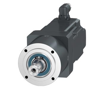
SIMOTICS S‑1FK2 and S-1FT2 servo planetary geared motors with coaxial gearboxes NRB, NRK, NLC and SIMOTICS S-1FT2 servo planetary geared motors with the NRBW, NRKW, NLCW angular gearboxes are highly dynamic, compact and economical drive units. The combinations, each composed of a servomotor with a high-performance coaxial or right-angle planetary gearbox, are suitable for a wide range of applications in an industrial environment.
These planetary geared motors are specified and delivered completely as a unit. All outstanding performance data are matched to the motor-gearbox combination.
Motors
High Dynamic
Wherever small masses have to be moved with maximum dynamics and precision, the 1FK2 and 1FT2 High Dynamic servomotors with low inertia really come into their own.
The lightweight and low-friction gearboxes in conjunction with inertia-optimized clamping systems allow the highest cycle rates in the application.
Compact
If larger loads need to be moved with precision and dynamically, a motor version with higher inertia is unavoidable for controllable operations. The 1FK2 and 1FT2 Compact servomotors with medium inertia and planetary gearboxes with higher transmission ratios enable even difficult inertia conditions to be mastered in terms of the control technology.
Planetary gearboxes
The three planetary gearboxes NRB(W), NRK(W), and NLC(W) can be mounted in all spatial positions without restriction and are maintenance-free thanks to their lifetime lubrication.
Coaxial gearboxes
NRB
NRB is the lightest gearbox with the highest power density. Thanks to its low friction bearing design it is suitable for high speeds and only generates a slight amount of heat.
Application areas:
- Packaging
- Food industry
- Pharmaceutical and medical systems
- Auxiliary axes in machine tools
NRK
The NRK series gearbox is suitable for higher radial and axial forces due to the large output bearing. This gearbox is also suitable for higher speeds thanks to low internal friction.
Application areas:
- Automation and mounting technology
- Packaging
- Auxiliary axes in machine tools
NLC
Thanks to the preloaded tapered roller bearing, the NLC gearbox has a high degree of stiffness and is perfectly suited for high radial and axial loads. The IP65 cover provides protection against dust and water.
Application areas:
- Automation and mounting technology
- Packaging
- Food industry
- Printing industry
- Auxiliary axes in machine tools
Angular gearboxes
An initial bevel gear stage makes the planetary gearboxes NRB, NRK and NLC also available as angular gearboxes NRBW, NRKW and NLCW.
The right-angle versions are the right choice in confined spaces.
Due to the additional angular stage, the losses in the angular gearboxes are slightly higher and the rated specifications are reduced in comparison to the comparable coaxial version.
|
|
|
Coaxial gearbox type
|
|
|
|
NRB
|
NRK
|
NLC
|
|
SIMOTICS S-1FK2 and S-1FT2 servo planetary geared motors
|
|

P_D211_XX_00805 |

P_D211_XX_00809 |

P_D211_XX_00801 |
|
Transmission ratio i
|
|
3 ... 512
|
3 ... 100
|
3 ... 100
|
|
Gearbox stages z
|
|
1, 2 and 3-stage
|
1 and 2-stage
|
1 and 2-stage
|
|
Torsional backlash φ2
|
'
|
6 ... 22
|
6 ... 19
|
7 ... 12
|
|
Gearbox type
- Eco planetary gearbox
- Straight gearing
- Life-long grease lubrication
- Average torsional backlash
|
|
IM B14 / IM V18 / IM V19
IP64
High input speeds thanks to low-friction bearing design

P_D211_XX_00715
|
IM B14 / IM V18 / IM V19
IP64
Large ball bearing, optimized for high radial and axial forces

P_D211_XX_00723
|
IM B5 / IM V1 / IM V3
IP65
Preloaded tapered roller bearing for best stiffness at highest loads

P_D211_XX_00719
|
|
Geared motor data for 200 ... 240 V 1/3 AC
|
|
Maximum torque M2max
|
Nm (lbf‑ft)
|
1.5 ... 1280 (1.11 ... 944)
|
1.4 ... 736 (1.03 ... 543)
|
3 ... 416 (2.21 ... 307)
|
|
Rated torque M2N
|
Nm (lbf‑ft)
|
0.2 ... 650 (0.15 ... 479)
|
0.1 ... 460 (0.07 ... 339)
|
0.14 ... 260 (0.10 ... 192)
|
|
Rated speed n2N
|
r/min
|
3 ... 1000
|
15 ... 1000
|
15 ... 500
|
|
Geared motor data for 380 ... 480 V 3 AC
|
|
Maximum torque M2max
|
Nm (lbf‑ft)
|
4.9 ... 1280 (3.61 ... 944)
|
4.7 ... 736 (3.47 ... 543)
|
4.7 ... 416 (3.47 ... 307)
|
|
Rated torque M2N
|
Nm (lbf‑ft)
|
0.8 ... 650 (0.59 ... 479)
|
0.54 ... 460 (0.40 ... 339)
|
0.35 ... 260 (0.26 ... 192)
|
|
Rated speed n2N
|
r/min
|
3 ... 1000
|
20 ... 750
|
25 ... 500
|
|
Suitability
|
|
Power density
|
|
+++
|
++
|
++
|
|
Bearing loading capacity
|
|
+
|
++
|
+++
|
|
Suitable for high speeds
|
|
++
|
++
|
+
|
|
Degree of protection
|
|
+
|
+
|
++
|
|
Options
|
|
Plain shaft / solid shaft with feather key
|
|
✓ / ✓
|
✓ / ✓
|
✓ / ✓
|
|
Standard lubrication / food-grade lubricant
|
|
✓ / ✓
|
✓ / ✓
|
✓ / ✓
|
|
|
|
Angular gearbox type
|
|
|
|
NRBW
|
NRKW
|
NLCW
|
|
SIMOTICS S-1FT2 servo planetary geared motors
|
|

P_D211_XX_01053 |

P_D211_XX_01049 |

P_D211_XX_01045 |
|
Transmission ratio i
|
|
3 ... 512
|
3 ... 100
|
3 ... 100
|
|
Gearbox stages z
|
|
1, 2 and 3-stage
|
1 and 2-stage
|
1 and 2-stage
|
|
Torsional backlash φ2
|
'
|
11 ... 28
|
11 ... 25
|
11 ... 18
|
|
Gearbox type
- Eco planetary gearbox
- Straight gearing
- Life-long grease lubrication
- Average torsional backlash
|
|
IM B14 / IM V18 / IM V19
IP64
High input speeds thanks to low-friction bearing design

P_D211_XX_01041
|
IM B14 / IM V18 / IM V19
IP64
Large ball bearing, optimized for high radial and axial forces

P_D211_XX_01044
|
IM B5 / IM V1 / IM V3
IP65
Preloaded tapered roller bearing for best stiffness at highest loads

P_D211_XX_01038
|
|
Geared motor data for 200 ... 240 V 1/3 AC
|
|
Maximum torque M2max
|
Nm (lbf‑ft)
|
1.4 ... 416 (1.03 ... 307)
|
1.5 ... 312 (1.11 ... 230)
|
3.5 ... 416 (2.58 ... 307)
|
|
Rated torque M2N
|
Nm (lbf‑ft)
|
0.1 ... 260 (0.07 ... 192)
|
0.11 ... 195 (0.08 ... 144)
|
0.12 ... 230 (0.09 ... 170)
|
|
Rated speed n2N
|
r/min
|
3 ... 1000
|
15 ... 1000
|
15 ... 375
|
|
Geared motor data for 380 ... 480 V 3 AC
|
|
Maximum torque M2max
|
Nm (lbf‑ft)
|
4.6 ... 416 (3.39 ... 307)
|
4.35 ... 312 (3.21 ... 230)
|
4.6 ... 416 (3.39 ... 307)
|
|
Rated torque M2N
|
Nm (lbf‑ft)
|
0.52 ... 260 (0.38 ... 192)
|
0.34 ... 195 (0.25 ... 144)
|
0.26 ... 230 (0.19 ... 170)
|
|
Rated speed n2N
|
r/min
|
6 ... 1000
|
15 ... 750
|
15 ... 375
|
|
Suitability
|
|
Power density
|
|
++
|
+
|
+
|
|
Bearing loading capacity
|
|
+
|
++
|
+++
|
|
Suitable for high speeds
|
|
+
|
+
|
•
|
|
Degree of protection
|
|
+
|
+
|
++
|
|
Options
|
|
Plain shaft / solid shaft with feather key
|
|
✓ / ✓
|
✓ / ✓
|
✓ / ✓
|
|
Standard lubrication / food-grade lubricant
|
|
✓ / ✓
|
✓ / ✓
|
✓ / ✓
|
Possible motor-gearbox combinations
Notes:
The geared motor can only be delivered as a unit – motor plus gearbox – (no individual gearboxes).
Not all combinations are possible.
For shaft design with feather key, the gearbox data only applies for pulsating loads. With alternating load / reversal of direction of rotation, limitation of the torque as a function of the number of load cycles is required (see Configuration Manual).
|
Coaxial gearbox type
|
Gearbox size
|
Motor
|
Order code
|
|
1FK2102 1)
|
1FK2 . 03
|
1FK2 . 04
|
1FK2 . 05
|
1FK2 . 06
|
1FK2208
|
1FK2210
|
Number of gearbox stages
|
|
|
|
1FT2102 1)
|
1FT2 . 03
|
1FT2 . 04
|
1FT2 . 05
|
1FT2 . 06
|
1FT2 . 08
|
1FT2210
|
|
|
|
|
For servo converters connected to 200 ... 240 V
|
For servo converters connected to 200 ... 240 V and 380 ... 480 V
|
1-stage
|
2-stage
|
3-stage
|
|
NRB

P_D211_XX_00712
|
040
|
✓
|
✓
|
–
|
–
|
–
|
–
|
–
|
A11
|
A12
|
A13
|
|
060
|
✓
|
✓
|
✓
|
✓
|
–
|
–
|
–
|
A21
|
A22
|
A23
|
|
080
|
–
|
✓
|
✓
|
✓
|
✓
|
–
|
–
|
A31
|
A32
|
A33
|
|
120
|
–
|
✓
|
✓
|
✓
|
✓
|
✓
|
–
|
A41
|
A42
|
A43
|
|
160
|
–
|
–
|
–
|
✓
|
✓
|
✓
|
–
|
A51
|
A52
|
A53
|
|
NRK

P_D211_XX_00720
|
050
|
✓
|
✓
|
–
|
–
|
–
|
–
|
–
|
B11
|
B12
|
–
|
|
070
|
✓
|
✓
|
✓
|
✓
|
–
|
–
|
–
|
B21
|
B22
|
–
|
|
090
|
–
|
✓
|
✓
|
✓
|
✓
|
–
|
–
|
B31
|
B32
|
–
|
|
120
|
–
|
✓
|
✓
|
✓
|
✓
|
✓
|
–
|
B41
|
B42
|
–
|
|
155
|
–
|
–
|
–
|
✓
|
✓
|
✓
|
✓
|
B51
|
B52
|
–
|
|
NLC

P_D211_XX_00716
|
060
|
✓
|
✓
|
✓
|
✓
|
–
|
–
|
–
|
C21
|
C22
|
–
|
|
080
|
–
|
✓
|
✓
|
✓
|
✓
|
–
|
–
|
C31
|
C32
|
–
|
|
120
|
–
|
✓
|
✓
|
✓
|
✓
|
✓
|
–
|
C41
|
C42
|
–
|
|
Angular gearbox type
|
Gearbox size
|
Motor
|
Order code
|
|
1FT2102 1)
|
1FT2 . 03
|
1FT2 . 04
|
1FT2 . 05
|
1FT2 . 06
|
1FT2208
|
1FT2210
|
Number of gearbox stages
|
|
|
|
For servo converters connected to 200 ... 240 V
|
For servo converters connected to 200 ... 240 V and 380 ... 480 V
|
1-stage
|
2-stage
|
3-stage
|
|
NRBW

P_D211_XX_01039
|
040
|
✓
|
–
|
–
|
–
|
–
|
–
|
–
|
A16
|
A17
|
A18
|
|
060
|
✓
|
✓
|
✓
|
–
|
–
|
–
|
–
|
A26
|
A27
|
A28
|
|
080
|
–
|
✓
|
✓
|
✓
|
–
|
–
|
–
|
A36
|
A37
|
A38
|
|
120
|
–
|
✓
|
✓
|
✓
|
✓
|
–
|
–
|
A46
|
A47
|
A48
|
|
NRKW

P_D211_XX_01042
|
050
|
✓
|
–
|
–
|
–
|
–
|
–
|
–
|
B16
|
B17
|
–
|
|
070
|
✓
|
✓
|
✓
|
–
|
–
|
–
|
–
|
B26
|
B27
|
–
|
|
090
|
–
|
✓
|
✓
|
✓
|
–
|
–
|
–
|
B36
|
B37
|
–
|
|
120
|
–
|
✓
|
✓
|
✓
|
✓
|
–
|
–
|
B46
|
B47
|
–
|
|
NLCW

P_D211_XX_01036
|
060
|
✓
|
✓
|
✓
|
–
|
–
|
–
|
–
|
C26
|
C27
|
–
|
|
080
|
–
|
✓
|
✓
|
✓
|
–
|
–
|
–
|
C36
|
C37
|
–
|
|
120
|
–
|
✓
|
✓
|
✓
|
✓
|
–
|
–
|
C46
|
C47
|
–
|
1) Only available for 200-240 V 1AC / 3AC
Gearbox ratio
|
Number of gearbox stages
|
Transmission ratio i
|
Order code
|
|
1-stage
|
3
|
R03
|
|
4
|
R04
|
|
5
|
R05
|
|
7
|
R07
|
|
8
|
R08
|
|
10
|
R10
|
|
2-stage
|
9
|
R09
|
|
12
|
R12
|
|
15
|
R15
|
|
16
|
R16
|
|
20
|
R20
|
|
25
|
R25
|
|
32
|
R32
|
|
40
|
R40
|
|
50
|
R50
|
|
64
|
R64
|
|
100
|
R00
|
|
3-stage
|
60
|
R60
|
|
80
|
R80
|
|
100
|
R01
|
|
120
|
R21
|
|
160
|
R61
|
|
200
|
R02
|
|
256
|
R52
|
|
320
|
R23
|
|
512
|
R51
|
Shaft extension options
The output shaft of the planetary gearbox can be ordered as a plain shaft for a friction-locked connection or optionally with a feather key for positive transmission.
A friction-locked connection free of backlash (plain shaft) is recommended for dynamic loads, particularly during reversals in operation.
For pulsating loads without reversals, a positive feather key connection is also suitable as an alternative.
Limitation of output torques for gearbox shaft with feather key
It must be ensured that the following torques are not exceeded at the output shaft for gearboxes with feather key and changing application loads. Regardless of this, other limitations such as maximum torque M2max, G or the rated torque M2N,G of the gearbox components are maintained.
|
Gearbox
|
Max. application torque M2 in feather key design in Nm
|
|
|
up to 10 million load changes
|
up to 100 million load changes
|
|
NRB040, NRBW040
|
9
|
7
|
|
NRB060, NRBW060
|
31
|
25
|
|
NRB080, NRBW080
|
68
|
54
|
|
NRB120, NRBW120
|
132
|
105
|
|
NRB160
|
401
|
319
|
|
NRK050, NRKW050
|
12
|
9
|
|
NRK070, NRKW070
|
No restriction
|
29
|
|
NRK090, NRKW090
|
84
|
67
|
|
NRK120, NRKW120
|
No restriction
|
190
|
|
NRK155
|
389
|
309
|
|
NLC060, NLCW060
|
37
|
29
|
|
NLC080, NLCW080
|
76
|
60
|
|
NLC120, NLCW120
|
239
|
190
|
Lubricant options
Planetary gearboxes can be optionally ordered with a food-grade lubricant.
This lubricant was developed for the food and pharmaceutical industries for unpredictable contact with products and packaging in the food, cosmetics, pharmaceutical and animal feed industries. NSF H1 registration ensures that the lubricant is compliant with FDA 21 CFR §178.3570.
|
Lubrication
|
Gearbox shaft extension
|
Order code
|
|
Standard lubrication
|
Smooth solid shaft
|
M00
|
|
Solid shaft with parallel key
|
M01
|
|
Food-safe lubricant 1)
|
Smooth solid shaft
|
M10
|
|
Solid shaft with parallel key
|
M11
|
1) For angular planetary gearboxes NRBW, NRKW, NLCW, the choice of the food-safe lubricant causes a reduction of the rating data from the following data tables. In this case, you can find the precise power and rating data in the data sheet from the online configurator:
www.siemens.com/spc
Option for orientation of the output for angular gearboxes
For angular geared motors, the gearbox output in relation to the connector points to the right by default (viewing the motor from the front). A different assembly can optionally be produced in accordance with the following table.
Note: The geared motor can be mounted in any spatial position.
ENG_723994.XML
General technical specifications for NRB, NRK, NLC coaxial gearboxes and NRBW, NRKW, NLCW angular gearboxes
Largest average input speed n1av, G and maximum input speed n1max, G
n
1av,G – largest average input speed: In each time window of 15 minutes, the average input speed must be below n1av,G
n1max,G – maximum input speed The maximum input speed n1max,G must never be exceeded.
The maximum speeds of the mounted motor can be found in the data sheet resulting from the configuration on the Siemens Product Configurator.
|
Coaxial gearbox type
|
Motor
|
Largest average input speed n1av, G in r/min
|
Maximum input speed n1max, G in r/min
|
|
NRB040, NRK050
|
1FK2102, 1FT2102
|
5000
|
18000
|
|
1FK2 . 03, 1FT2 . 03
|
4500
|
|
NRB060, NRK070, NLC060
|
1FK2102, 1FT2102
1FK2 . 03, 1FT2 . 03
1FK2 . 04, 1FT2 . 04
|
4500
|
13000
|
|
1FK2 . 05, 1FT2 . 05
|
4000
|
|
NRB080, NRK090, NLC080
|
1FK2 . 03, 1FT2 . 03
1FK2 . 04, 1FT2 . 04
1FK2 . 05, 1FT2 . 05
|
4000
|
7000
|
|
1FK2 . 06, 1FT2 . 06
|
3500
|
|
NRB120, NRK120, NLC120
|
1FK2 . 03, 1FT2 . 03
1FK2 . 04, 1FT2 . 04
1FK2 . 05, 1FT2 . 05
1FK2 . 06, 1FT2 . 06
|
3500
|
6500
|
|
1FK2208, 1FT2 . 08
1FK2210, 1FT2210
|
3000
|
|
NRB160, NRK155
|
1FK2 . 05, 1FT2 . 05
1FK2 . 06, 1FT2 . 06
1FK2208, 1FT2 . 08
1FK2210, 1FT2210
|
3000
|
5500
|
|
Angular gearbox type
|
Motor
|
Largest average input speed n1av, G in r/min
|
Maximum input speed n1max, G in r/min
|
|
NRBW040, NRKW050
|
1FT2102
|
5000
|
18000
|
|
1FT2 . 03
|
4500
|
|
NRBW060, NRKW070, NLCW060
|
1FT2102
1FT2 . 03
1FT2 . 04
|
4500
|
13000
|
|
1FT2 . 05
|
4000
|
|
NRBW080, NRKW090, NLCW080
|
1FT2 . 03
1FT2 . 04
1FT2 . 05
|
4000
|
7000
|
|
1FT2 . 06
|
3500
|
|
NRBW120, NRKW120, NLCW120
|
1FT2 . 03
1FT2 . 04
1FT2 . 05
1FT2 . 06
|
3500
|
6500
|
|
1FT2208
1FT2210
|
3000
|
Technical specifications for NRB coaxial gearbox
M
2N, G – Rated torque for gearbox components
An endurance strength calculation becomes necessary if this torque is exceeded (see Configuration Manual). For the feather key version, the gearbox nominal torque is only permissible as a pulsating load or a reduction must be carried out depending on the number of load changes (see Components and Options).
|
Transmission ratio i
|
M
2N, G – Rated torque for gearbox components in Nm
|
|
|
Gearbox
|
|
|
NRB040
|
NRB060
|
NRB080
|
NRB120
|
NRB160
|
|
1-stage
|
|
3
|
11
|
28
|
85
|
115
|
400
|
|
4
|
15
|
38
|
115
|
155
|
450
|
|
5
|
14
|
40
|
110
|
195
|
450
|
|
7
|
8.5
|
25
|
65
|
135
|
–
|
|
8
|
6
|
18
|
50
|
120
|
450
|
|
10
|
5
|
15
|
38
|
95
|
–
|
|
2-stage
|
|
9
|
16.5
|
44
|
130
|
210
|
–
|
|
12
|
20
|
44
|
120
|
260
|
800
|
|
15
|
18
|
44
|
110
|
230
|
700
|
|
16
|
20
|
44
|
120
|
260
|
800
|
|
20
|
20
|
44
|
120
|
260
|
800
|
|
25
|
18
|
40
|
110
|
230
|
700
|
|
32
|
20
|
44
|
120
|
260
|
800
|
|
40
|
18
|
40
|
110
|
230
|
700
|
|
64
|
7.5
|
18
|
50
|
120
|
450
|
|
3-stage
|
|
60
|
20
|
44
|
110
|
260
|
–
|
|
80
|
20
|
44
|
120
|
260
|
–
|
|
100
|
20
|
44
|
120
|
260
|
–
|
|
120
|
18
|
44
|
110
|
230
|
–
|
|
160
|
20
|
44
|
120
|
260
|
–
|
|
200
|
18
|
40
|
110
|
230
|
–
|
|
256
|
20
|
44
|
120
|
260
|
–
|
|
320
|
18
|
40
|
110
|
230
|
–
|
|
512
|
7.5
|
18
|
50
|
120
|
–
|
M
2max, G – Maximum output torque of the gearbox components
This torque must not be exceeded during operation. It is permissible for a maximum of 30000 revolutions of the output shaft. An endurance strength configuration of the gearbox becomes necessary, if the output torques up to M2max, G are used (see Configuration Manual).
|
Transmission ratio i
|
M
2max, G – Maximum output torque of the gearbox components in Nm
|
|
|
Gearbox
|
|
|
NRB040
|
NRB060
|
NRB080
|
NRB120
|
NRB160
|
|
1-stage
|
|
3
|
17.5
|
45
|
136
|
184
|
640
|
|
4
|
24
|
61
|
184
|
248
|
720
|
|
5
|
22
|
64
|
176
|
312
|
720
|
|
7
|
13.5
|
40
|
104
|
216
|
–
|
|
8
|
10
|
29
|
80
|
192
|
720
|
|
10
|
8
|
24
|
61
|
152
|
–
|
|
2-stage
|
|
9
|
26
|
70
|
208
|
336
|
–
|
|
12
|
32
|
70
|
192
|
416
|
1280
|
|
15
|
29
|
70
|
176
|
368
|
1120
|
|
16
|
32
|
70
|
192
|
416
|
1280
|
|
20
|
32
|
70
|
192
|
416
|
1280
|
|
25
|
29
|
64
|
176
|
368
|
1120
|
|
32
|
32
|
70
|
192
|
416
|
1280
|
|
40
|
29
|
64
|
176
|
368
|
1120
|
|
64
|
12
|
29
|
80
|
192
|
720
|
|
3-stage
|
|
60
|
32
|
70
|
176
|
416
|
–
|
|
80
|
32
|
70
|
192
|
416
|
–
|
|
100
|
32
|
70
|
192
|
416
|
–
|
|
120
|
29
|
70
|
176
|
368
|
–
|
|
160
|
32
|
70
|
192
|
416
|
–
|
|
200
|
29
|
64
|
176
|
368
|
–
|
|
256
|
32
|
70
|
192
|
416
|
–
|
|
320
|
29
|
64
|
176
|
368
|
–
|
|
512
|
12
|
29
|
80
|
192
|
–
|
M
2Em.Off – Emergency Off output torque of the gearbox components
The Emergency Off torque can be tolerated a maximum of 1000 times within the gearbox service life without causing unacceptable damage to the gearbox. This code can be used to check whether the torques, caused by very rare operating faults, can damage the gearbox.
|
Transmission ratio i
|
M
2Em.Off – Emergency Off output torque of the gear components in Nm
|
|
|
Gearbox
|
|
|
NRB040
|
NRB060
|
NRB080
|
NRB120
|
NRB160
|
|
1-stage
|
|
3
|
22.5
|
66
|
180
|
390
|
800
|
|
4
|
30
|
88
|
240
|
520
|
900
|
|
5
|
36
|
80
|
220
|
500
|
900
|
|
7
|
26
|
80
|
178
|
340
|
–
|
|
8
|
27
|
80
|
190
|
380
|
900
|
|
10
|
27
|
80
|
200
|
480
|
–
|
|
2-stage
|
|
9
|
33
|
88
|
260
|
500
|
–
|
|
12
|
40
|
88
|
240
|
520
|
1600
|
|
15
|
36
|
88
|
220
|
500
|
1400
|
|
16
|
40
|
88
|
240
|
520
|
1600
|
|
20
|
40
|
88
|
240
|
520
|
1600
|
|
25
|
36
|
80
|
220
|
500
|
1400
|
|
32
|
40
|
88
|
240
|
520
|
1600
|
|
40
|
36
|
80
|
220
|
500
|
1400
|
|
64
|
27
|
80
|
190
|
380
|
900
|
|
3-stage
|
|
60
|
40
|
88
|
220
|
520
|
–
|
|
80
|
40
|
88
|
240
|
520
|
–
|
|
100
|
40
|
88
|
240
|
520
|
–
|
|
120
|
36
|
88
|
220
|
500
|
–
|
|
160
|
40
|
88
|
240
|
520
|
–
|
|
200
|
36
|
80
|
220
|
500
|
–
|
|
256
|
40
|
88
|
240
|
520
|
–
|
|
320
|
36
|
80
|
220
|
500
|
–
|
|
512
|
27
|
80
|
190
|
380
|
–
|
η
G– Efficiency of the gearbox components under full load
The exact values for the efficiency are, to some extent, dependent on the frame size of the mounted motor and can be found in the data sheet resulting from the configuration in the Siemens Product Configurator.
In the partial load range, especially when the gearbox is cold, the efficiency of the gearbox is always lower than at operating speed.
The gear losses are already taken into account in the characteristic curves and in the following characteristic data of the geared motor or its components: M2,0, M2,max, M0,M, Mmax,M
A reduction of this characteristic curve and the characteristics on efficiency is not necessary.
|
Transmission ratio i
|
η
G– Efficiency of the gearbox components under full load in %
|
|
|
Gearbox
|
|
|
NRB040
|
NRB060
|
NRB080
|
NRB120
|
NRB160
|
|
1-stage
|
|
3
|
98
|
98
|
98
|
98
|
98
|
|
4
|
98
|
98
|
98
|
98
|
98
|
|
5
|
97 ... 98
|
98
|
98
|
98
|
98
|
|
7
|
96 ... 97
|
96 ... 97
|
97
|
97
|
–
|
|
8
|
94 ... 96
|
95 ... 97
|
96 ... 97
|
97
|
97
|
|
10
|
92 ... 95
|
94 ... 96
|
94 ... 96
|
97
|
–
|
|
2-stage
|
|
9
|
96 ... 97
|
96 ... 97
|
96 ... 97
|
97
|
–
|
|
12
|
95 ... 96
|
95 ... 96
|
96 ... 97
|
96
|
96
|
|
15
|
95 ... 96
|
95 ... 96
|
95 ... 96
|
96
|
96
|
|
16
|
95 ... 96
|
95 ... 96
|
95 ... 96
|
96
|
96
|
|
20
|
94 ... 96
|
94 ... 96
|
95 ... 96
|
96
|
96
|
|
25
|
93 ... 95
|
93 ... 95
|
94 ... 95
|
95
|
95
|
|
32
|
92 ... 95
|
92 ... 95
|
93 ... 95
|
95
|
95
|
|
40
|
91 ... 94
|
91 ... 94
|
92 ... 94
|
94
|
94
|
|
64
|
76 ... 86
|
78 ... 87
|
81 ... 89
|
89
|
90
|
|
3-stage
|
|
60
|
88 ... 92
|
88 ... 92
|
88 ... 92
|
92
|
–
|
|
80
|
85 ... 90
|
86 ... 91
|
87 ... 91
|
91
|
–
|
|
100
|
83 ... 89
|
83 ... 89
|
85 ... 90
|
90
|
–
|
|
120
|
79 ... 87
|
81 ... 88
|
82 ... 89
|
88
|
–
|
|
160
|
77 ... 86
|
77 ... 86
|
80 ... 88
|
87
|
–
|
|
200
|
71 ... 82
|
72 ... 83
|
75 ... 85
|
84
|
–
|
|
256
|
69 ... 81
|
69 ... 81
|
73 ... 84
|
83
|
–
|
|
320
|
62 ... 76
|
63 ... 77
|
67 ... 80
|
79
|
–
|
|
512
|
31 ... 48
|
34 ... 51
|
38 ... 57
|
58
|
–
|
cT2 – Torsional rigidity of the gearbox (with reference to the output)
The exact values for the torsional rigidity are dependent on the motor-gearbox combination and can be found in the data sheet resulting from the configuration in the Siemens Product Configurator.
|
Transmission ratio i
|
C
T2 – Torsional rigidity of the gearbox in Nm/ '
|
|
|
Gearbox
|
|
|
NRB040
|
NRB060
|
NRB080
|
NRB120
|
NRB160
|
|
1-stage
|
|
3
|
0.65 ... 0.75
|
2.2 ... 2.6
|
7.2 ... 7.9
|
17.5 ... 18.5
|
57.5 ... 59.5
|
|
4
|
0.85 ... 0.95
|
2.4 ... 2.8
|
9.2 ... 10.1
|
19 ... 20.5
|
65 ... 68
|
|
5
|
0.9 ... 0.95
|
2.5 ... 2.8
|
9.4 ... 10.2
|
19.5 ... 21
|
66 ... 69
|
|
7
|
0.8 ... 0.85
|
2.3 ... 2.5
|
8.1 ... 8.7
|
17.5 ... 18.5
|
–
|
|
8
|
0.8 ... 0.85
|
2.2 ... 2.5
|
8 ... 8.4
|
17 ... 18
|
60 ... 62
|
|
10
|
0.75
|
2 ... 2.2
|
7.5 ... 7.9
|
15.5 ... 16.4
|
–
|
|
2-stage
|
|
9
|
0.75 ... 0.8
|
2.4 ... 2.7
|
7.9 ... 8.4
|
19 ... 20
|
–
|
|
12
|
0.9 ... 1
|
2.5 ... 2.8
|
9.6 ... 10.3
|
20.5 ... 22
|
70 ... 73
|
|
15
|
0.9 ... 1
|
2.4 ... 2.7
|
9.5 ... 10.2
|
20 ... 21.5
|
69 ... 73
|
|
16
|
0.95 ... 1
|
2.5 ... 2.8
|
9.8 ... 10.5
|
20.5 ... 22
|
72 ... 75
|
|
20
|
0.95 ... 1
|
2.5 ... 2.8
|
9.8 ... 10.4
|
20.5 ... 22
|
72 ... 75
|
|
25
|
0.95 ... 1
|
2.5 ... 2.8
|
9.7 ... 10.3
|
20 ... 21.5
|
70 ... 74
|
|
32
|
0.95 ... 1
|
2.5 ... 2.8
|
9.7 ... 10.3
|
20.5 ... 22
|
71 ... 75
|
|
40
|
0.95 ... 1
|
2.5 ... 2.8
|
9.6 ... 10.2
|
20 ... 21.5
|
70 ... 73
|
|
64
|
0.8 ... 0.85
|
2.3 ... 2.5
|
7.9 ... 8.3
|
17.5 ... 18.5
|
61 ... 63
|
|
3-stage
|
|
60
|
0.95 ... 1
|
2.5 ... 2.8
|
9.7 ... 10.3
|
20.5 ... 22
|
–
|
|
80
|
0.95 ... 1
|
2.5 ... 2.8
|
9.8 ... 10.5
|
20.5 ... 22
|
–
|
|
100
|
0.95 ... 1
|
2.5 ... 2.8
|
9.8 ... 10.4
|
20.5 ... 22
|
–
|
|
120
|
0.95 ... 1
|
2.4 ... 2.7
|
9.6 ... 10.2
|
20 ... 21.5
|
–
|
|
160
|
0.95 ... 1
|
2.5 ... 2.8
|
9.8 ... 10.4
|
20.5 ... 22
|
–
|
|
200
|
0.95 ... 1
|
2.5 ... 2.8
|
9.7 ... 10.3
|
20 ... 21.5
|
–
|
|
256
|
0.95 ... 1
|
2.5 ... 2.8
|
9.7 ... 10.3
|
20.5 ... 22
|
–
|
|
320
|
0.95 ... 1
|
2.5 ... 2.8
|
9.6 ... 10.2
|
20 ... 21.5
|
–
|
|
512
|
0.8 ... 0.85
|
2.3 ... 2.5
|
7.9 ... 8.3
|
17.5 ... 18.5
|
–
|
φ
2 – Torsional backlash of the gearbox on the gear output
|
Gearbox stages z
|
φ
2 – Torsional backlash of the gearbox on the gearbox output in '
|
|
|
Gearbox
|
|
|
NRB040
|
NRB060
|
NRB080
|
NRB120
|
NRB160
|
|
1-stage
|
15
|
10
|
7
|
7
|
6
|
|
2-stage
|
19
|
12
|
9
|
9
|
10
|
|
3-stage
|
22
|
15
|
11
|
11
|
–
|
Permissible shaft loading capacity
The limit values shown for the bearing load refer to equivalent forces to be determined mathematically, whose effect is equivalent to the forces occurring in the load profile.
They only apply to radial and axial loads. Axial forces up to maximum FA = 0.24 × FR are permissible in case of superimposition.
They apply to the output speed of 100 r/min and in case of radial force for a force application point in the center of the shaft or for centrally applied axial force. For other speeds or force application points, the permissible radial forces must be obtained from the radial force diagrams of the Configuration Manual.
|
|
Permissible shaft loading capacity, radial and axial forces in Nm
|
|
|
Gearbox
|
|
|
NRB040
|
NRB060
|
NRB080
|
NRB120
|
NRB160
|
|
Average radial force FR eq
|
|
|
|
|
|
|
|
200
|
400
|
750
|
1750
|
5000
|
|
|
160
|
340
|
650
|
1500
|
4200
|
|
Maximum radial force FR max
|
200
|
700
|
1250
|
2000
|
5000
|
|
Average axial force FA eq
|
|
|
|
|
|
|
|
200
|
500
|
1000
|
2500
|
7000
|
|
|
160
|
450
|
900
|
2100
|
6000
|
|
Maximum axial force FA max
|
240
|
800
|
1600
|
3800
|
11000
|
m
G - Weight of the gearbox components
The weight of the assigned motors and the total weight of the geared motors are in the data sheet resulting from the configuration of the motor or the gear motor in the Siemens Product Configurator.
|
Transmission ratio i
|
m
G - Weight of the gearbox components in kg
|
|
|
Gearbox
|
|
|
NRB040
|
NRB060
|
NRB080
|
NRB120
|
NRB160
|
|
|
Motor
|
|
|
1FK2102
1FT2102
|
1FK2 . 03
1FT2 . 03
|
1FK2102
1FT2102
1FK2 . 03
1FT2 . 03
|
1FK2 . 04
1FT2 . 04
1FK2 . 05
1FT2 . 05
|
1FK2 . 03
1FT2 . 03
1FK2 . 04
1FT2 . 04
1FK2 . 05
1FT2 . 05
|
1FK2 . 06
1FT2 . 06
|
1FK2 . 03
1FT2 . 03
1FK2 . 04
1FT2 . 04
1FK2 . 05
1FT2 . 05
1FK2 . 06
1FT2 . 06
|
1FK2208
1FT2 . 08
|
1FK2 . 05
1FT2 . 05
1FK2 . 06
1FT2 . 06
1FK2208
1FT2 . 08
|
|
1-stage
|
|
3
|
0.34
|
0.60
|
0.87
|
1.7
|
2.1
|
3.2
|
5.7
|
7.4
|
17
|
|
4
|
0.35
|
0.60
|
0.88
|
1.4
|
2.1
|
3.2
|
5.7
|
7.8
|
17
|
|
5
|
0.35
|
0.60
|
0.89
|
1.4
|
2.2
|
3.2
|
5.8
|
7.8
|
17
|
|
7
|
0.35
|
0.60
|
0.88
|
1.4
|
2.1
|
3.2
|
5.7
|
7.8
|
–
|
|
8
|
0.35
|
0.68
|
0.88
|
1.4
|
2.1
|
3.2
|
5.7
|
7.0
|
17
|
|
10
|
0.35
|
0.61
|
0.89
|
1.4
|
2.2
|
3.2
|
5.7
|
7.8
|
–
|
|
2-stage
|
|
9
|
0.43
|
0.69
|
1.1
|
1.9
|
2.6
|
3.7
|
7.4
|
9.2
|
–
|
|
12
|
0.43
|
0.69
|
1.1
|
1.9
|
2.6
|
3.7
|
7.4
|
9.2
|
23
|
|
15
|
0.43
|
0.69
|
1.1
|
1.6
|
2.6
|
3.7
|
7.5
|
9.3
|
23
|
|
16
|
0.44
|
0.69
|
1.1
|
1.6
|
2.6
|
3.7
|
7.5
|
9.5
|
23
|
|
20
|
0.44
|
0.69
|
1.1
|
1.6
|
2.6
|
3.7
|
7.5
|
9.6
|
23
|
|
25
|
0.44
|
0.69
|
1.1
|
1.6
|
2.7
|
3.7
|
7.5
|
9.6
|
23
|
|
32
|
0.44
|
0.77
|
1.1
|
1.6
|
2.7
|
3.7
|
7.5
|
8.9
|
23
|
|
40
|
0.44
|
0.77
|
1.1
|
1.6
|
2.7
|
3.7
|
7.6
|
8.9
|
23
|
|
64
|
0.44
|
0.78
|
1.1
|
1.6
|
2.7
|
3.7
|
7.6
|
8.9
|
23
|
|
3-stage
|
|
60
|
0.52
|
0.78
|
1.3
|
1.8
|
3.1
|
4.2
|
9.2
|
11
|
–
|
|
80
|
0.53
|
0.78
|
1.3
|
1.8
|
3.1
|
4.2
|
9.2
|
11
|
–
|
|
100
|
0.53
|
0.78
|
1.3
|
1.8
|
3.1
|
4.2
|
9.3
|
11
|
–
|
|
120
|
0.53
|
0.78
|
1.3
|
1.8
|
3.2
|
4.2
|
9.3
|
11
|
–
|
|
160
|
0.53
|
0.86
|
1.3
|
1.8
|
3.1
|
4.2
|
9.3
|
11
|
–
|
|
200
|
0.53
|
0.86
|
1.3
|
1.8
|
3.2
|
4.2
|
9.4
|
11
|
–
|
|
256
|
0.54
|
0.87
|
1.3
|
1.8
|
3.2
|
4.2
|
9.4
|
11
|
–
|
|
320
|
0.53
|
0.87
|
1.3
|
1.8
|
3.2
|
4.3
|
9.4
|
11
|
–
|
|
512
|
0.54
|
0.87
|
1.3
|
1.8
|
3.2
|
4.3
|
9.4
|
11
|
–
|
Technical specifications for NRK coaxial gearbox
M
2N, G – Rated torque for gearbox components
An endurance strength calculation becomes necessary if this torque is exceeded (see Configuration Manual). For the feather key version, the gearbox nominal torque is only permissible as a pulsating load or a reduction must be carried out depending on the number of load changes (see Components and Options).
|
Transmission ratio i
|
M
2N, G – Rated torque for gearbox components in Nm
|
|
|
Gearbox
|
|
|
NRK050
|
NRK070
|
NRK090
|
NRK120
|
NRK155
|
|
1-stage
|
|
3
|
11
|
28
|
85
|
115
|
–
|
|
4
|
15
|
33
|
90
|
155
|
460
|
|
5
|
13
|
30
|
82
|
172
|
445
|
|
7
|
8.5
|
25
|
65
|
135
|
–
|
|
8
|
6
|
18
|
50
|
120
|
–
|
|
10
|
5
|
15
|
38
|
95
|
210
|
|
2-stage
|
|
9
|
12
|
33
|
97
|
157
|
–
|
|
12
|
15
|
33
|
90
|
195
|
–
|
|
15
|
13
|
33
|
82
|
172
|
–
|
|
16
|
15
|
33
|
90
|
195
|
460
|
|
20
|
15
|
33
|
90
|
195
|
460
|
|
25
|
13
|
30
|
82
|
172
|
445
|
|
32
|
15
|
33
|
90
|
195
|
–
|
|
40
|
13
|
30
|
82
|
172
|
460
|
|
50
|
–
|
–
|
–
|
–
|
445
|
|
64
|
7.5
|
18
|
50
|
120
|
–
|
|
100
|
5
|
15
|
38
|
95
|
210
|
M
2max, G – Maximum output torque of the gearbox components
This torque must not be exceeded during operation. It is permissible for a maximum of 30000 revolutions of the output shaft. An endurance strength configuration of the gearbox becomes necessary, if the output torques up to M2max, G are used (see Configuration Manual).
|
Transmission ratio i
|
M
2max, G – Maximum output torque of the gearbox components in Nm
|
|
|
Gearbox
|
|
|
NRK050
|
NRK070
|
NRK090
|
NRK120
|
NRK155
|
|
1-stage
|
|
3
|
17.5
|
45
|
136
|
184
|
–
|
|
4
|
24
|
53
|
144
|
248
|
736
|
|
5
|
21
|
48
|
131
|
275
|
712
|
|
7
|
13.5
|
40
|
104
|
216
|
–
|
|
8
|
9.5
|
29
|
80
|
192
|
–
|
|
10
|
8
|
24
|
61
|
152
|
336
|
|
2-stage
|
|
9
|
19
|
53
|
155
|
251
|
–
|
|
12
|
24
|
53
|
144
|
312
|
–
|
|
15
|
21
|
53
|
131
|
275
|
–
|
|
16
|
24
|
53
|
144
|
312
|
736
|
|
20
|
24
|
53
|
144
|
312
|
736
|
|
25
|
21
|
48
|
131
|
275
|
712
|
|
32
|
24
|
53
|
144
|
312
|
–
|
|
40
|
21
|
48
|
131
|
275
|
736
|
|
50
|
–
|
–
|
–
|
–
|
712
|
|
64
|
12
|
29
|
80
|
192
|
–
|
|
100
|
8
|
24
|
61
|
152
|
336
|
M
2Em.Off – Emergency Off output torque of the gearbox components
The Emergency Off torque can be tolerated a maximum of 1000 times within the gearbox service life without causing unacceptable damage to the gearbox. This code can be used to check whether the torques, caused by very rare operating faults, can damage the gearbox.
|
Transmission ratio i
|
M
2Em.Off – Emergency Off output torque of the gear components in Nm
|
|
|
Gearbox
|
|
|
NRK050
|
NRK070
|
NRK090
|
NRK120
|
NRK155
|
|
1-stage
|
|
3
|
22.5
|
66
|
180
|
390
|
–
|
|
4
|
30
|
88
|
240
|
520
|
920
|
|
5
|
36
|
80
|
220
|
500
|
890
|
|
7
|
26
|
80
|
178
|
340
|
–
|
|
8
|
27
|
80
|
190
|
380
|
–
|
|
10
|
27
|
80
|
200
|
480
|
420
|
|
2-stage
|
|
9
|
33
|
88
|
260
|
500
|
–
|
|
12
|
40
|
88
|
240
|
520
|
–
|
|
15
|
36
|
88
|
220
|
500
|
–
|
|
16
|
40
|
88
|
240
|
520
|
920
|
|
20
|
40
|
88
|
240
|
520
|
920
|
|
25
|
36
|
80
|
220
|
500
|
890
|
|
32
|
40
|
88
|
240
|
520
|
–
|
|
40
|
36
|
80
|
220
|
500
|
920
|
|
50
|
–
|
–
|
–
|
–
|
890
|
|
64
|
27
|
80
|
190
|
380
|
–
|
|
100
|
27
|
80
|
200
|
480
|
420
|
η
G– Efficiency of the gearbox components under full load
The exact values for the efficiency are, to some extent, dependent on the frame size of the mounted motor and can be found in the data sheet resulting from the configuration in the Siemens Product Configurator.
In the partial load range, especially when the gearbox is cold, the efficiency of the gearbox is always lower than at operating speed.
The gear losses are already taken into account in the characteristic curves and in the following characteristic data of the geared motor or its components: M2,0, M2,max, M0,M, Mmax,M
A reduction of this characteristic curve and the characteristics on efficiency is not necessary.
|
Transmission ratio i
|
η
G– Efficiency of the gearbox components under full load in %
|
|
|
Gearbox
|
|
|
NRK050
|
NRK070
|
NRK090
|
NRK120
|
NRK155
|
|
1-stage
|
|
3
|
97 ... 98
|
97 ... 98
|
98
|
98
|
–
|
|
4
|
97 ... 98
|
97 ... 98
|
98
|
98
|
98
|
|
5
|
97 ... 98
|
97
|
97 ... 98
|
98
|
98
|
|
7
|
95 ... 97
|
96 ... 97
|
96 ... 97
|
97
|
–
|
|
8
|
94 ... 96
|
95 ... 96
|
96 ... 97
|
97
|
–
|
|
10
|
92 ... 95
|
93 ... 95
|
94 ... 96
|
96
|
97
|
|
2-stage
|
|
9
|
95 ... 96
|
95 ... 96
|
96 ... 97
|
96
|
–
|
|
12
|
95 ... 96
|
95 ... 96
|
95 ... 96
|
96
|
–
|
|
15
|
94 ... 95
|
94 ... 95
|
94 ... 96
|
96
|
–
|
|
16
|
94 ... 95
|
94 ... 95
|
94 ... 96
|
96
|
96
|
|
20
|
93 ... 95
|
93 ... 95
|
94 ... 95
|
95
|
96
|
|
25
|
91 ... 94
|
92 ... 94
|
92 ... 95
|
95
|
95 ... 96
|
|
32
|
91 ... 94
|
91 ... 94
|
92 ... 94
|
94
|
–
|
|
40
|
88 ... 92
|
89 ... 93
|
90 ... 94
|
93
|
94 ... 95
|
|
50
|
–
|
–
|
–
|
–
|
94 ... 95
|
|
64
|
76 ... 86
|
78 ... 86
|
81 ... 89
|
89
|
–
|
|
100
|
60 ... 75
|
67 ... 80
|
69 ... 82
|
83
|
84 ... 88
|
cT2 – Torsional rigidity of the gearbox (with reference to the output)
The exact values for the torsional rigidity are dependent on the motor-gearbox combination and can be found in the data sheet resulting from the configuration in the Siemens Product Configurator.
|
Transmission ratio i
|
C
T2 – Torsional rigidity of the gearbox in Nm/ '
|
|
|
Gearbox
|
|
|
NRK050
|
NRK070
|
NRK090
|
NRK120
|
NRK155
|
|
1-stage
|
|
3
|
0.7 ... 0.75
|
4 ... 5.1
|
9.7 ... 10.8
|
29.5 ... 31.5
|
–
|
|
4
|
0.9 ... 1
|
4.7 ... 5.7
|
13.6 ... 15.3
|
35.5 ... 38.5
|
65 ... 70
|
|
5
|
0.95 ... 1
|
5 ... 5.9
|
14 ... 15.5
|
36.5 ... 39.5
|
68 ... 72
|
|
7
|
0.85
|
4.2 ... 4.6
|
11.4 ... 12.2
|
29.5 ... 31
|
–
|
|
8
|
0.85
|
4.1 ... 4.5
|
11.1 ... 11.8
|
28.5 ... 30.5
|
–
|
|
10
|
0.75 ... 0.8
|
3.5 ... 3.8
|
10.1 ... 10.6
|
24.5 ... 25.5
|
54.5 ... 56.5
|
|
2-stage
|
|
9
|
0.8 ... 0.85
|
4.7 ... 5.2
|
11 ... 11.7
|
34 ... 36.5
|
–
|
|
12
|
1 ... 1.05
|
5.1 ... 5.7
|
14.6 ... 15.7
|
39.5 ... 43
|
–
|
|
15
|
1 ... 1.05
|
4.8 ... 5.3
|
14.4 ... 15.5
|
37.5 ... 40.5
|
–
|
|
16
|
1 ... 1.05
|
5.2 ... 5.8
|
15 ... 16.1
|
40 ... 43.5
|
69 ... 73
|
|
20
|
1 ... 1.05
|
5.2 ... 5.7
|
15 ... 16.1
|
40 ... 43.5
|
70 ... 73
|
|
25
|
1 ... 1.05
|
5.3 ... 5.8
|
14.7 ... 15.8
|
37.5 ... 41
|
70 ... 73
|
|
32
|
1 ... 1.05
|
5.1 ... 5.6
|
14.8 ... 15.8
|
39.5 ... 43
|
–
|
|
40
|
1 ... 1.05
|
5.2 ... 5.8
|
14.6 ... 15.6
|
37.5 ... 40.5
|
69 ... 72
|
|
50
|
–
|
–
|
–
|
–
|
69 ... 73
|
|
64
|
0.85 ... 0.9
|
4.2 ... 4.6
|
11 ... 11.5
|
30 ... 31.5
|
–
|
|
100
|
0.7
|
3.3 ... 3.6
|
9.7 ... 10.1
|
21 ... 22
|
55 ... 57
|
φ
2 – Torsional backlash of the gearbox on the gear output
|
Gearbox stages z
|
φ
2 – Torsional backlash of the gearbox on the gearbox output in '
|
|
|
Gearbox
|
|
|
NRK050
|
NRK070
|
NRK090
|
NRK120
|
NRK155
|
|
1-stage
|
15
|
10
|
7
|
7
|
6
|
|
2-stage
|
19
|
12
|
9
|
9
|
9
|
Permissible shaft loading capacity
The limit values shown for the bearing load refer to equivalent forces to be determined mathematically, whose effect is equivalent to the forces occurring in the load profile.
They only apply to radial and axial loads. Axial forces up to maximum FA = 0.24 × FR are permissible in case of superimposition.
They apply to the output speed of 100 r/min and in case of radial force for a force application point in the center of the shaft or for centrally applied axial force. For other speeds or force application points, the permissible radial forces must be obtained from the radial force diagrams of the Configuration Manual.
|
|
Permissible shaft loading capacity, radial and axial forces in Nm
|
|
|
Gearbox
|
|
|
NRK050
|
NRK070
|
NRK090
|
NRK120
|
NRK155
|
|
Average radial force FR eq
|
|
|
|
|
|
|
|
800
|
1050
|
1900
|
2500
|
5200
|
|
|
700
|
900
|
1700
|
2150
|
4600
|
|
Maximum radial force FR max
|
1300
|
1650
|
3100
|
4000
|
8400
|
|
Average axial force FA eq
|
|
|
|
|
|
|
|
1000
|
1350
|
2000
|
4000
|
7000
|
|
|
800
|
1000
|
1500
|
3000
|
6000
|
|
Maximum axial force FA max
|
1000
|
2100
|
3800
|
5900
|
11000
|
m
G - Weight of the gearbox components
The weight of the assigned motors and the total weight of the geared motors are in the data sheet resulting from the configuration of the motor or the gear motor in the Siemens Product Configurator.
|
Transmission ratio i
|
m
G - Weight of the gearbox components in kg
|
|
|
Gearbox
|
|
|
NRK050
|
NRK070
|
NRK090
|
NRK120
|
NRK155
|
|
|
Motor
|
|
|
1FK2102
1FT2102
|
1FK2 . 03
1FT2 . 03
|
1FK2102
1FT2102
1FK2 . 03
1FT2 . 03
1FK2 . 04
1FT2 . 04
|
1FK2 . 05
1FT2 . 05
|
1FK2 . 03
1FT2 . 03
1FK2 . 04
1FT2 . 04
1FK2 . 05
1FT2 . 05
|
1FK2 . 06
1FT2 . 06
|
1FK2 . 03
1FT2 . 03
1FK2 . 04
1FT2 . 04
1FK2 . 05
1FT2 . 05
1FK2 . 06
1FT2 . 06
|
1FK2208
1FT2 . 08
|
1FK2 . 05
1FT2 . 05
1FK2 . 06
1FT2 . 06
1FK2208
1FT2 . 08
|
1FK2210
1FT2210
|
|
1-stage
|
|
3
|
0.61
|
0.86
|
1.4
|
2.2
|
3.3
|
4.3
|
7.5
|
9.2
|
–
|
–
|
|
4
|
0.61
|
0.87
|
1.4
|
1.9
|
3.3
|
4.3
|
7.5
|
9.6
|
17
|
22
|
|
5
|
0.61
|
0.87
|
1.4
|
2
|
3.3
|
4.3
|
7.5
|
9.6
|
17
|
22
|
|
7
|
0.62
|
0.87
|
1.4
|
2
|
3.3
|
4.3
|
7.5
|
9.6
|
–
|
–
|
|
8
|
0.61
|
0.95
|
1.4
|
2
|
3.3
|
4.4
|
7.5
|
8.9
|
–
|
–
|
|
10
|
0.63
|
0.88
|
1.4
|
2
|
3.3
|
4.4
|
7.6
|
9.7
|
17
|
22
|
|
2-stage
|
|
9
|
0.77
|
1.0
|
1.7
|
2.5
|
3.9
|
5.0
|
9.4
|
11
|
–
|
–
|
|
12
|
0.77
|
1.0
|
1.7
|
2.5
|
3.9
|
5.0
|
9.4
|
11
|
–
|
–
|
|
15
|
0.77
|
1.0
|
1.7
|
2.2
|
3.9
|
5.0
|
9.4
|
11
|
–
|
–
|
|
16
|
0.77
|
1.0
|
1.7
|
2.2
|
3.9
|
5.0
|
9.4
|
11
|
22
|
28
|
|
20
|
0.77
|
1.0
|
1.7
|
2.2
|
3.9
|
5.0
|
9.4
|
12
|
22
|
28
|
|
25
|
0.77
|
1.0
|
1.7
|
2.3
|
4.0
|
5.0
|
9.5
|
12
|
22
|
28
|
|
32
|
0.77
|
1.1
|
1.7
|
2.3
|
4.0
|
5.0
|
9.5
|
11
|
–
|
–
|
|
40
|
0.78
|
1.1
|
1.7
|
2.3
|
4.0
|
5.0
|
9.5
|
11
|
22
|
28
|
|
50
|
–
|
–
|
–
|
–
|
–
|
–
|
–
|
–
|
22
|
28
|
|
64
|
0.78
|
1.1
|
1.7
|
2.3
|
4.0
|
5.1
|
9.6
|
11
|
–
|
–
|
|
100
|
0.81
|
1.1
|
1.9
|
2.4
|
4.1
|
5.1
|
9.7
|
12
|
22
|
28
|
Technical specifications for NLC coaxial gearbox
M
2N, G – Rated torque for gearbox components
An endurance strength calculation becomes necessary if this torque is exceeded (see Configuration Manual). For the feather key version, the gearbox nominal torque is only permissible as a pulsating load or a reduction must be carried out depending on the number of load changes (see Components and Options).
|
Transmission ratio i
|
M
2N, G – Rated torque for gearbox components in Nm
|
|
|
Gearbox
|
|
|
NLC060
|
NLC080
|
NLC120
|
|
1-stage
|
|
3
|
28
|
85
|
115
|
|
4
|
38
|
115
|
155
|
|
5
|
40
|
110
|
195
|
|
7
|
25
|
65
|
135
|
|
8
|
18
|
50
|
120
|
|
10
|
15
|
38
|
95
|
|
2-stage
|
|
9
|
44
|
130
|
210
|
|
12
|
44
|
120
|
260
|
|
15
|
44
|
110
|
230
|
|
16
|
44
|
120
|
260
|
|
20
|
44
|
120
|
260
|
|
25
|
40
|
110
|
230
|
|
32
|
44
|
120
|
260
|
|
40
|
40
|
110
|
230
|
|
64
|
18
|
50
|
120
|
|
100
|
15
|
38
|
95
|
M
2max, G – Maximum output torque of the gearbox components
This torque must not be exceeded during operation. It is permissible for a maximum of 30000 revolutions of the output shaft. An endurance strength configuration of the gearbox becomes necessary, if the output torques up to M2max, G are used (see Configuration Manual).
|
Transmission ratio i
|
M
2max, G – Maximum output torque of the gearbox components in Nm
|
|
|
Gearbox
|
|
|
NLC060
|
NLC080
|
NLC120
|
|
1-stage
|
|
3
|
45
|
136
|
184
|
|
4
|
61
|
148
|
248
|
|
5
|
64
|
176
|
312
|
|
7
|
40
|
104
|
216
|
|
8
|
29
|
80
|
192
|
|
10
|
24
|
61
|
152
|
|
2-stage
|
|
9
|
70
|
208
|
336
|
|
12
|
70
|
192
|
416
|
|
15
|
70
|
176
|
368
|
|
16
|
70
|
192
|
416
|
|
20
|
70
|
192
|
416
|
|
25
|
64
|
176
|
368
|
|
32
|
70
|
192
|
416
|
|
40
|
64
|
176
|
368
|
|
64
|
29
|
80
|
192
|
|
100
|
24
|
61
|
152
|
M
2Em.Off – Emergency Off output torque of the gearbox components
The Emergency Off torque can be tolerated a maximum of 1000 times within the gearbox service life without causing unacceptable damage to the gearbox. This code can be used to check whether the torques, caused by very rare operating faults, can damage the gearbox.
|
Transmission ratio i
|
M
2Em.Off – Emergency Off output torque of the gear components in Nm
|
|
|
Gearbox
|
|
|
NLC060
|
NLC080
|
NLC120
|
|
1-stage
|
|
3
|
66
|
180
|
390
|
|
4
|
88
|
240
|
520
|
|
5
|
80
|
220
|
500
|
|
7
|
80
|
178
|
340
|
|
8
|
80
|
190
|
380
|
|
10
|
80
|
200
|
480
|
|
2-stage
|
|
9
|
88
|
260
|
500
|
|
12
|
88
|
240
|
520
|
|
15
|
88
|
220
|
500
|
|
16
|
88
|
240
|
520
|
|
20
|
88
|
240
|
520
|
|
25
|
80
|
220
|
500
|
|
32
|
88
|
240
|
520
|
|
40
|
80
|
220
|
500
|
|
64
|
80
|
190
|
380
|
|
100
|
80
|
200
|
480
|
η
G– Efficiency of the gearbox components under full load
The exact values for the efficiency are, to some extent, dependent on the frame size of the mounted motor and can be found in the data sheet resulting from the configuration in the Siemens Product Configurator.
In the partial load range, especially when the gearbox is cold, the efficiency of the gearbox is always lower than at operating speed.
The gear losses are already taken into account in the characteristic curves and in the following characteristic data of the geared motor or its components: M2,0, M2,max, M0,M, Mmax,M
A reduction of this characteristic curve and the characteristics on efficiency is not necessary.
|
Transmission ratio i
|
η
G– Efficiency of the gearbox components under full load in %
|
|
|
Gearbox
|
|
|
NLC060
|
NLC080
|
NLC120
|
|
1-stage
|
|
3
|
96
|
97
|
97
|
|
4
|
96 ... 97
|
97
|
97
|
|
5
|
96 ... 97
|
97
|
97
|
|
7
|
94 ... 95
|
95 ... 96
|
96
|
|
8
|
93 ... 94
|
94 ... 96
|
96
|
|
10
|
91 ... 93
|
92 ... 94
|
96
|
|
2-stage
|
|
9
|
95 ... 96
|
96
|
96
|
|
12
|
94 ... 95
|
95 ... 96
|
96
|
|
15
|
94 ... 95
|
94 ... 95
|
96
|
|
16
|
94 ... 95
|
94 ... 96
|
96
|
|
20
|
93 ... 95
|
94 ... 95
|
95
|
|
25
|
92 ... 94
|
93 ... 95
|
95
|
|
32
|
91 ... 94
|
93 ... 95
|
95
|
|
40
|
90 ... 93
|
91 ... 94
|
94
|
|
64
|
77 ... 85
|
80 ... 88
|
89
|
|
100
|
66 ... 78
|
68 ... 81
|
83
|
cT2 – Torsional rigidity of the gearbox (with reference to the output)
The exact values for the torsional rigidity are dependent on the motor-gearbox combination and can be found in the data sheet resulting from the configuration in the Siemens Product Configurator.
|
Transmission ratio i
|
C
T2 – Torsional rigidity of the gearbox in Nm/ '
|
|
|
Gearbox
|
|
|
NLC060
|
NLC080
|
NLC120
|
|
1-stage
|
|
3
|
3.4 ... 4.1
|
8.2 ... 8.9
|
21.5 ... 22
|
|
4
|
3.9 ... 4.5
|
10.9 ... 11.8
|
24.5 ... 25.5
|
|
5
|
4 ... 4.6
|
11.2 ... 11.9
|
25 ... 26
|
|
7
|
3.5 ... 3.8
|
9.4 ... 9.9
|
21.5 ... 22
|
|
8
|
3.4 ... 3.7
|
9.2 ... 9.6
|
21 ... 22
|
|
10
|
3 ... 3.2
|
8.5 ... 8.9
|
18.5 ... 19.5
|
|
2-stage
|
|
9
|
3.8 ... 4.2
|
9.2 ... 9.6
|
23.5 ... 24.5
|
|
12
|
4.1 ... 4.5
|
11.5 ... 12.1
|
26 ... 27.5
|
|
15
|
3.9 ... 4.2
|
11.4 ... 12
|
25.5 ... 26.5
|
|
16
|
4.2 ... 4.6
|
11.8 ... 12.3
|
26.5 ... 27.5
|
|
20
|
4.1 ... 4.5
|
11.8 ... 12.3
|
26.5 ... 27.5
|
|
25
|
4.2 ... 4.6
|
11.6 ... 12.1
|
25.5 ... 26.5
|
|
32
|
4.1 ... 4.5
|
11.5 ... 12.2
|
26 ... 27.5
|
|
40
|
4.2 ... 4.5
|
11.5 ... 12
|
25.5 ... 26.5
|
|
64
|
3.5 ... 3.8
|
9.2 ... 9.5
|
21.5 ... 22.5
|
|
100
|
2.9 ... 3.1
|
8.2 ... 8.5
|
16.7 ... 17
|
φ
2 – Torsional backlash of the gearbox on the gear output
|
Gearbox stages z
|
φ
2 – Torsional backlash of the gearbox on the gearbox output in '
|
|
|
Gearbox
|
|
|
NLC060
|
NLC080
|
NLC120
|
|
1-stage
|
10
|
7
|
7
|
|
2-stage
|
12
|
9
|
9
|
Permissible shaft loading capacity
The limit values shown for the bearing load refer to equivalent forces to be determined mathematically, whose effect is equivalent to the forces occurring in the load profile.
They only apply to radial and axial loads. Axial forces up to maximum FA = 0.4 × FR are permissible in case of superimposition.
They apply to the output speed of 100 r/min and in case of radial force for a force application point in the center of the shaft or for centrally applied axial force. For other speeds or force application points, the permissible radial forces must be obtained from the radial force diagrams of the Configuration Manual.
|
|
Permissible shaft loading capacity, radial and axial forces in Nm
|
|
|
Gearbox
|
|
|
NLC060
|
NLC080
|
NLC120
|
|
Average radial force FR eq
|
|
|
|
|
|
3200
|
5500
|
6000
|
|
|
3200
|
4800
|
5400
|
|
Maximum radial force FR max
|
3200
|
5500
|
6000
|
|
Average axial force FA eq
|
|
|
|
|
|
4400
|
6400
|
8000
|
|
|
3900
|
5700
|
7000
|
|
Maximum axial force FA max
|
4400
|
6400
|
8000
|
m
G - Weight of the gearbox components
The weight of the assigned motors and the total weight of the geared motors are in the data sheet resulting from the configuration of the motor or the gear motor in the Siemens Product Configurator.
|
Transmission ratio i
|
m
G - Weight of the gearbox components in kg
|
|
|
Gearbox
|
|
|
NLC060
|
NLC080
|
NLC120
|
|
|
Motor
|
|
|
1FK2102
1FT2102
1FK2 . 03
1FT2 . 03
1FK2 . 04
1FT2 . 04
|
1FK2 . 05
1FT2 . 05
|
1FK2 . 03
1FT2 . 03
1FK2 . 04
1FT2 . 04
1FK2 . 05
1FT2 . 05
|
1FK2 . 06
1FT2 . 06
|
1FK2 . 03
1FT2 . 03
1FK2 . 04
1FT2 . 04
1FK2 . 05
1FT2 . 05
1FK2 . 06
1FT2 . 06
|
1FK2208
1FT2 . 08
|
|
1-stage
|
|
3
|
1.6
|
2.4
|
3.0
|
4.1
|
6.9
|
8.7
|
|
4
|
1.6
|
2.1
|
3.0
|
4.1
|
6.9
|
9.0
|
|
5
|
1.6
|
2.1
|
3.1
|
4.1
|
7.0
|
9.1
|
|
7
|
1.6
|
2.1
|
3.0
|
4.1
|
7.0
|
9.1
|
|
8
|
1.6
|
2.1
|
3.0
|
4.1
|
6.9
|
8.2
|
|
10
|
1.6
|
2.1
|
3.1
|
4.1
|
7.0
|
9.1
|
|
2-stage
|
|
9
|
1.7
|
2.6
|
3.6
|
4.6
|
8.6
|
10
|
|
12
|
1.8
|
2.6
|
3.5
|
4.6
|
8.6
|
10
|
|
15
|
1.7
|
2.3
|
3.5
|
4.6
|
8.7
|
10
|
|
16
|
1.8
|
2.3
|
3.5
|
4.6
|
8.6
|
11
|
|
20
|
1.8
|
2.3
|
3.5
|
4.6
|
8.7
|
11
|
|
25
|
1.8
|
2.3
|
3.6
|
4.6
|
8.7
|
11
|
|
32
|
1.8
|
2.3
|
3.6
|
4.6
|
8.7
|
10
|
|
40
|
1.8
|
2.3
|
3.6
|
4.6
|
8.8
|
10
|
|
64
|
1.8
|
2.3
|
3.6
|
4.6
|
8.7
|
10
|
|
100
|
1.8
|
2.3
|
3.6
|
4.7
|
8.9
|
11
|
Technical specifications for NRBW angular gearboxes
M
2N, G – Rated torque for gearbox components
An endurance strength calculation becomes necessary if this torque is exceeded (see Configuration Manual). For the feather key version, the gearbox nominal torque is only permissible as a pulsating load or a reduction must be carried out depending on the number of load changes (see Components and Options).
|
Transmission ratio i
|
M
2N, G – Rated torque for gearbox components in Nm (lb-ft)
|
|
|
Gearbox
|
|
|
NRBW040
|
NRBW060
|
NRBW080
|
NRBW120
|
|
1-stage
|
|
3
|
4.5
|
14
|
40
|
80
|
|
4
|
6
|
19
|
53
|
105
|
|
5
|
7.5
|
24
|
67
|
130
|
|
7
|
8.5
|
25
|
65
|
135
|
|
8
|
6
|
18
|
50
|
120
|
|
10
|
5
|
15
|
38
|
95
|
|
2-stage
|
|
9
|
16.5
|
44
|
130
|
210
|
|
12
|
20
|
44
|
120
|
260
|
|
15
|
18
|
44
|
110
|
230
|
|
16
|
20
|
44
|
120
|
260
|
|
20
|
20
|
44
|
120
|
260
|
|
25
|
18
|
40
|
110
|
230
|
|
32
|
20
|
44
|
120
|
260
|
|
40
|
18
|
40
|
110
|
230
|
|
64
|
7.5
|
18
|
50
|
120
|
|
3-stage
|
|
60
|
20
|
44
|
110
|
260
|
|
80
|
20
|
44
|
120
|
260
|
|
100
|
20
|
44
|
120
|
260
|
|
120
|
18
|
44
|
110
|
230
|
|
160
|
20
|
44
|
120
|
260
|
|
200
|
18
|
40
|
110
|
230
|
|
256
|
20
|
44
|
120
|
260
|
|
320
|
18
|
40
|
110
|
230
|
|
512
|
7.5
|
18
|
50
|
120
|
M
2max, G – Maximum output torque of the gearbox components
This torque must not be exceeded during operation. It is permissible for a maximum of 30000 revolutions of the output shaft. An endurance strength configuration of the gearbox becomes necessary, if the output torques up to M2max, G are used (see Configuration Manual).
|
Transmission ratio i
|
M
2max, G – Maximum output torque of the gearbox components in Nm (lb-ft)
|
|
|
Gearbox
|
|
|
NRBW040
|
NRBW060
|
NRBW080
|
NRBW120
|
|
1-stage
|
|
3
|
7.5
|
22
|
64
|
128
|
|
4
|
10
|
30
|
85
|
168
|
|
5
|
12
|
38
|
107
|
208
|
|
7
|
13.5
|
40
|
104
|
216
|
|
8
|
10
|
29
|
80
|
192
|
|
10
|
8
|
24
|
61
|
152
|
|
2-stage
|
|
9
|
26
|
70
|
208
|
336
|
|
12
|
32
|
70
|
192
|
416
|
|
15
|
29
|
70
|
176
|
368
|
|
16
|
32
|
70
|
192
|
416
|
|
20
|
32
|
70
|
192
|
416
|
|
25
|
29
|
64
|
176
|
368
|
|
32
|
32
|
70
|
192
|
416
|
|
40
|
29
|
64
|
176
|
368
|
|
64
|
12
|
29
|
80
|
192
|
|
3-stage
|
|
60
|
32
|
70
|
176
|
416
|
|
80
|
32
|
70
|
192
|
416
|
|
100
|
32
|
70
|
192
|
416
|
|
120
|
29
|
70
|
176
|
368
|
|
160
|
32
|
70
|
192
|
416
|
|
200
|
29
|
64
|
176
|
368
|
|
256
|
32
|
70
|
192
|
416
|
|
320
|
29
|
64
|
176
|
368
|
|
512
|
12
|
29
|
80
|
192
|
M
2Em.Off – Emergency Off output torque of the gearbox components
The Emergency Off torque can be tolerated a maximum of 1000 times within the gearbox service life without causing unacceptable damage to the gearbox. This code can be used to check whether the torques, caused by very rare operating faults, can damage the gearbox.
|
Transmission ratio i
|
M
2Em.Off – Emergency Off output torque of the gear components in Nm (lb-ft)
|
|
|
Gearbox
|
|
|
NRBW040
|
NRBW060
|
NRBW080
|
NRBW120
|
|
1-stage
|
|
3
|
22.5
|
66
|
180
|
360
|
|
4
|
28
|
86
|
240
|
474
|
|
5
|
35
|
80
|
220
|
500
|
|
7
|
26
|
80
|
178
|
340
|
|
8
|
27
|
80
|
190
|
380
|
|
10
|
25
|
70
|
170
|
430
|
|
2-stage
|
|
9
|
33
|
88
|
260
|
500
|
|
12
|
40
|
88
|
240
|
520
|
|
15
|
36
|
88
|
220
|
500
|
|
16
|
40
|
88
|
240
|
520
|
|
20
|
40
|
88
|
240
|
520
|
|
25
|
36
|
80
|
220
|
500
|
|
32
|
40
|
88
|
240
|
520
|
|
40
|
36
|
80
|
220
|
500
|
|
64
|
27
|
80
|
190
|
380
|
|
3-stage
|
|
60
|
40
|
88
|
220
|
520
|
|
80
|
40
|
88
|
240
|
520
|
|
100
|
40
|
88
|
240
|
520
|
|
120
|
36
|
88
|
220
|
500
|
|
160
|
40
|
88
|
240
|
520
|
|
200
|
36
|
80
|
220
|
500
|
|
256
|
40
|
88
|
240
|
520
|
|
320
|
36
|
80
|
220
|
500
|
|
512
|
27
|
80
|
190
|
380
|
η
G– Efficiency of the gearbox components under full load
The exact values for the efficiency are, to some extent, dependent on the frame size of the mounted motor and can be found in the data sheet resulting from the configuration in the Siemens Product Configurator.
In the partial load range, especially when the gearbox is cold, the efficiency of the gearbox is always lower than at operating speed.
The gear losses are already taken into account in the characteristic curves and in the following characteristic data of the geared motor or its components: M2,0, M2,max, M0,M, Mmax,M
A reduction of this characteristic curve and the characteristics on efficiency is not necessary.
|
Transmission ratio i
|
η
G– Efficiency of the gearbox components under full load in%
|
|
|
Gearbox
|
|
|
NRBW040
|
NRBW060
|
NRBW080
|
NRBW120
|
|
1-stage
|
|
3
|
94
|
95
|
95
|
95
|
|
4
|
94
|
95
|
95
|
95
|
|
5
|
94
|
95
|
95
|
95
|
|
7
|
94
|
94
|
95
|
95
|
|
8
|
92
|
93
|
94
|
95
|
|
10
|
90
|
92
|
93
|
94
|
|
2-stage
|
|
9
|
94
|
94
|
94
|
94
|
|
12
|
94
|
94
|
94
|
94
|
|
15
|
93
|
93
|
93
|
94
|
|
16
|
93
|
93
|
93
|
94
|
|
20
|
92
|
92
|
93
|
93
|
|
25
|
91
|
91
|
92
|
92
|
|
32
|
91
|
91
|
92
|
92
|
|
40
|
89
|
89
|
90
|
91
|
|
64
|
75
|
77
|
80
|
84
|
|
3-stage
|
|
60
|
86
|
86
|
87
|
88
|
|
80
|
84
|
84
|
86
|
87
|
|
100
|
82
|
82
|
84
|
85
|
|
120
|
78
|
80
|
81
|
82
|
|
160
|
76
|
76
|
79
|
81
|
|
200
|
70
|
71
|
74
|
77
|
|
256
|
68
|
68
|
72
|
75
|
|
320
|
61
|
62
|
66
|
70
|
|
512
|
31
|
33
|
38
|
46
|
cT2 – Torsional rigidity of the gearbox (with reference to the output)
The exact values for the torsional rigidity are dependent on the motor-gearbox combination and can be found in the data sheet resulting from the configuration in the Siemens Product Configurator.
|
Transmission ratio i
|
C
T2 – Torsional rigidity of the gearbox in Nm/ '
|
|
|
Gearbox
|
|
|
NRBW040
|
NRBW060
|
NRBW080
|
NRBW120
|
|
1-stage
|
|
3
|
0.45
|
1.6
|
4.1
|
10
|
|
4
|
0.63
|
2.0
|
6.0
|
14
|
|
5
|
0.73
|
2.2
|
7.0
|
15
|
|
7
|
0.78
|
2.2
|
7.5
|
17
|
|
8
|
0.78
|
2.2
|
7.5
|
17
|
|
10
|
0.73
|
2.2
|
7.8
|
16
|
|
2-stage
|
|
9
|
0.73
|
2.4
|
7.4
|
18
|
|
12
|
0.93
|
2.6
|
9.3
|
20
|
|
15
|
0.93
|
2.5
|
9.5
|
20
|
|
16
|
0.95
|
2.6
|
9.7
|
21
|
|
20
|
0.98
|
2.6
|
9.9
|
21
|
|
25
|
0.95
|
2.7
|
9.8
|
20
|
|
32
|
0.98
|
2.7
|
10
|
21
|
|
40
|
0.98
|
2.7
|
9.9
|
21
|
|
64
|
0.83
|
2.4
|
8.1
|
18
|
|
3-stage
|
|
60
|
0.98
|
2.7
|
10
|
21
|
|
80
|
0.98
|
2.7
|
10
|
21
|
|
100
|
0.98
|
2.7
|
10
|
21
|
|
120
|
0.98
|
2.6
|
9.9
|
21
|
|
160
|
0.98
|
2.7
|
10
|
21
|
|
200
|
0.98
|
2.7
|
10
|
21
|
|
256
|
0.98
|
2.7
|
10
|
21
|
|
320
|
0.98
|
2.7
|
9.9
|
21
|
|
512
|
0.83
|
2.4
|
8.1
|
18
|
φ
2 – Torsional backlash of the gearbox on the gear output
|
Gearbox stages z
|
φ
2 – Torsional backlash of the gearbox on the gearbox output in '
|
|
|
Gearbox
|
|
|
NRBW040
|
NRBW060
|
NRBW080
|
NRBW120
|
|
1-stage
|
21
|
16
|
13
|
11
|
|
2-stage
|
25
|
18
|
15
|
13
|
|
3-stage
|
28
|
21
|
17
|
15
|
Permissible shaft loading capacity
The limit values shown for the bearing load refer to equivalent forces to be determined mathematically, whose effect is equivalent to the forces occurring in the load profile.
They only apply to radial and axial loads. Axial forces up to maximum FA = 0.24 × FR are permissible in case of superimposition.
They apply to the output speed of 100 r/min and in case of radial force for a force application point in the center of the shaft or for centrally applied axial force. For other speeds or force application points, the permissible radial forces must be obtained from the radial force diagrams of the Configuration Manual.
|
|
Permissible shaft loading capacity, radial and axial forces in Nm (lb-ft)
|
|
|
Gearbox
|
|
|
NRBW040
|
NRBW060
|
NRBW080
|
NRBW120
|
|
Average radial force FR eq
|
|
|
|
|
|
|
200
|
400
|
750
|
1750
|
|
|
160
|
340
|
650
|
1500
|
|
Maximum radial force FR max
|
200
|
700
|
1250
|
2000
|
|
Average axial force FA eq
|
|
|
|
|
|
|
200
|
500
|
1000
|
2500
|
|
|
160
|
450
|
900
|
2100
|
|
Maximum axial force FA max
|
240
|
800
|
1600
|
3800
|
m
G - Weight of the gearbox components
The weight of the assigned motors and the total weight of the geared motors are in the data sheet resulting from the configuration of the motor or the gear motor in the Siemens Product Configurator.
|
Transmission ratio i
|
m
G - Weight of the gearbox components in kg (lb)
|
|
|
Gearbox
|
|
|
NRBW040
|
NRBW060
|
NRBW080
|
NRBW120
|
|
|
Motor
|
|
|
1FT2102
|
1FT2102
1FT2 . 03
|
1FT2 . 04
|
1FT2 . 03
1FT2 . 04
|
1FT2105
|
1FT2205
|
1FT2 . 03
1FT2 . 04
1FT2 . 05
|
1FT2 . 06
|
|
1-stage
|
|
3
|
0.55
|
1.6
|
1.8
|
3.6
|
4.0
|
3.8
|
9.6
|
10
|
|
4
|
0.56
|
1.6
|
1.8
|
3.6
|
4.0
|
3.8
|
9.7
|
10
|
|
5
|
0.56
|
1.6
|
1.8
|
3.6
|
4.0
|
3.8
|
9.7
|
10
|
|
7
|
0.56
|
1.6
|
1.8
|
3.6
|
4.0
|
3.8
|
9.7
|
10
|
|
8
|
0.56
|
1.6
|
1.8
|
3.6
|
4.0
|
3.8
|
9.7
|
10
|
|
10
|
0.56
|
1.6
|
1.8
|
3.6
|
4.0
|
3.8
|
9.7
|
10
|
|
2-stage
|
|
9
|
0.64
|
1.8
|
2.0
|
4.1
|
4.5
|
4.3
|
11
|
12
|
|
12
|
0.64
|
1.8
|
2.0
|
4.1
|
4.5
|
4.3
|
11
|
12
|
|
15
|
0.64
|
1.8
|
2.0
|
4.1
|
4.5
|
4.3
|
11
|
12
|
|
16
|
0.64
|
1.8
|
2.0
|
4.0
|
4.5
|
4.2
|
11
|
12
|
|
20
|
0.65
|
1.8
|
2.0
|
4.1
|
4.5
|
4.3
|
11
|
12
|
|
25
|
0.64
|
1.8
|
2.0
|
4.1
|
4.5
|
4.3
|
12
|
12
|
|
32
|
0.65
|
1.8
|
2.0
|
4.1
|
4.5
|
4.3
|
12
|
12
|
|
40
|
0.65
|
1.8
|
2.0
|
4.1
|
4.5
|
4.3
|
12
|
12
|
|
64
|
0.65
|
1.8
|
2.0
|
4.1
|
4.5
|
4.3
|
12
|
12
|
|
3-stage
|
|
60
|
0.74
|
2.0
|
2.2
|
4.5
|
5.0
|
4.7
|
13
|
14
|
|
80
|
0.74
|
2.0
|
2.2
|
4.5
|
5.0
|
4.7
|
13
|
14
|
|
100
|
0.74
|
2.0
|
2.2
|
4.6
|
5.0
|
4.8
|
13
|
14
|
|
120
|
0.74
|
2.0
|
2.2
|
4.6
|
5.0
|
4.8
|
13
|
14
|
|
160
|
0.74
|
2.0
|
2.2
|
4.6
|
5.0
|
4.8
|
13
|
14
|
|
200
|
0.74
|
2.0
|
2.2
|
4.6
|
5.0
|
4.8
|
13
|
14
|
|
256
|
0.74
|
2.0
|
2.2
|
4.6
|
5.0
|
4.8
|
13
|
14
|
|
320
|
0.74
|
2.0
|
2.2
|
4.6
|
5.1
|
4.8
|
13
|
14
|
|
512
|
0.75
|
2.0
|
2.2
|
4.6
|
5.1
|
4.8
|
13
|
14
|
Technical specifications for NRKW angular gearboxes
M
2N, G – Rated torque for gearbox components
An endurance strength calculation becomes necessary if this torque is exceeded (see Configuration Manual). For the feather key version, the gearbox nominal torque is only permissible as a pulsating load or a reduction must be carried out depending on the number of load changes (see Components and Options).
|
Transmission ratio i
|
M
2N, G – Rated torque for gearbox components in Nm (lb-ft)
|
|
|
Gearbox
|
|
|
NRKW050
|
NRKW070
|
NRKW090
|
NRKW120
|
|
1-stage
|
|
3
|
4.5
|
14
|
40
|
80
|
|
4
|
6
|
19
|
53
|
105
|
|
5
|
7.5
|
24
|
67
|
130
|
|
7
|
8.5
|
25
|
65
|
135
|
|
8
|
6
|
18
|
50
|
120
|
|
10
|
5
|
15
|
38
|
95
|
|
2-stage
|
|
9
|
12
|
33
|
97
|
157
|
|
12
|
15
|
33
|
90
|
195
|
|
15
|
13
|
33
|
82
|
172
|
|
16
|
15
|
33
|
90
|
195
|
|
20
|
15
|
33
|
90
|
195
|
|
25
|
13
|
30
|
82
|
172
|
|
32
|
15
|
33
|
90
|
195
|
|
40
|
13
|
30
|
82
|
172
|
|
64
|
7.5
|
18
|
50
|
120
|
|
100
|
5
|
15
|
38
|
95
|
M
2max, G – Maximum output torque of the gearbox components
This torque must not be exceeded during operation. It is permissible for a maximum of 30000 revolutions of the output shaft. An endurance strength configuration of the gearbox becomes necessary, if the output torques up to M2max, G are used (see Configuration Manual).
|
Transmission ratio i
|
M
2max, G – Maximum output torque of the gearbox components in Nm (lb-ft)
|
|
|
Gearbox
|
|
|
NRKW050
|
NRKW070
|
NRKW090
|
NRKW120
|
|
1-stage
|
|
3
|
7
|
22
|
64
|
128
|
|
4
|
10
|
30
|
85
|
168
|
|
5
|
12
|
38
|
107
|
208
|
|
7
|
13.5
|
40
|
104
|
216
|
|
8
|
10
|
29
|
80
|
192
|
|
10
|
8
|
24
|
61
|
152
|
|
2-stage
|
|
9
|
19
|
53
|
155
|
251
|
|
12
|
24
|
53
|
144
|
312
|
|
15
|
21
|
53
|
131
|
275
|
|
16
|
24
|
53
|
144
|
312
|
|
20
|
24
|
53
|
144
|
312
|
|
25
|
21
|
48
|
131
|
275
|
|
32
|
24
|
53
|
144
|
312
|
|
40
|
21
|
48
|
131
|
275
|
|
64
|
12
|
29
|
80
|
192
|
|
100
|
8
|
24
|
61
|
152
|
M
2Em.Off – Emergency Off output torque of the gearbox components
The Emergency Off torque can be tolerated a maximum of 1000 times within the gearbox service life without causing unacceptable damage to the gearbox. This code can be used to check whether the torques, caused by very rare operating faults, can damage the gearbox.
|
Transmission ratio i
|
M
2Em.Off – Emergency Off output torque of the gear components in Nm (lb-ft)
|
|
|
Gearbox
|
|
|
NRKW050
|
NRKW070
|
NRKW090
|
NRKW120
|
|
1-stage
|
|
3
|
22.5
|
66
|
180
|
360
|
|
4
|
28
|
86
|
240
|
474
|
|
5
|
35
|
80
|
220
|
500
|
|
7
|
26
|
80
|
178
|
340
|
|
8
|
27
|
80
|
190
|
380
|
|
10
|
25
|
70
|
170
|
430
|
|
2-stage
|
|
9
|
33
|
88
|
260
|
500
|
|
12
|
40
|
88
|
240
|
520
|
|
15
|
36
|
88
|
220
|
500
|
|
16
|
40
|
88
|
240
|
520
|
|
20
|
40
|
88
|
240
|
520
|
|
25
|
36
|
80
|
220
|
500
|
|
32
|
40
|
88
|
240
|
520
|
|
40
|
36
|
80
|
220
|
500
|
|
64
|
27
|
80
|
190
|
380
|
|
100
|
27
|
80
|
170
|
430
|
η
G– Efficiency of the gearbox components under full load
The exact values for the efficiency are, to some extent, dependent on the frame size of the mounted motor and can be found in the data sheet resulting from the configuration in the Siemens Product Configurator.
In the partial load range, especially when the gearbox is cold, the efficiency of the gearbox is always lower than at operating speed.
The gear losses are already taken into account in the characteristic curves and in the following characteristic data of the geared motor or its components: M2,0, M2,max, M0,M, Mmax,M
A reduction of this characteristic curve and the characteristics on efficiency is not necessary.
|
Transmission ratio i
|
η
G– Efficiency of the gearbox components under full load in%
|
|
|
Gearbox
|
|
|
NRKW050
|
NRKW070
|
NRKW090
|
NRKW120
|
|
1-stage
|
|
3
|
94
|
94
|
95
|
95
|
|
4
|
94
|
94
|
95
|
95
|
|
5
|
94
|
95
|
95
|
95
|
|
7
|
94
|
94
|
95
|
95
|
|
8
|
92
|
93
|
94
|
94
|
|
10
|
90
|
91
|
92
|
94
|
|
2-stage
|
|
9
|
93
|
93
|
94
|
94
|
|
12
|
93
|
93
|
93
|
94
|
|
15
|
92
|
92
|
93
|
93
|
|
16
|
92
|
92
|
93
|
93
|
|
20
|
91
|
91
|
92
|
93
|
|
25
|
90
|
90
|
91
|
91
|
|
32
|
89
|
89
|
90
|
91
|
|
40
|
87
|
87
|
89
|
90
|
|
64
|
75
|
76
|
80
|
84
|
|
100
|
59
|
65
|
69
|
75
|
cT2 – Torsional rigidity of the gearbox (with reference to the output)
The exact values for the torsional rigidity are dependent on the motor-gearbox combination and can be found in the data sheet resulting from the configuration in the Siemens Product Configurator.
|
Transmission ratio i
|
C
T2 – Torsional rigidity of the gearbox in Nm/ '
|
|
|
Gearbox
|
|
|
NRK0W50
|
NRKW070
|
NRKW090
|
NRKW120
|
|
1-stage
|
|
3
|
0.45
|
2.3
|
4.8
|
13
|
|
4
|
0.65
|
3.2
|
7.5
|
20
|
|
5
|
0.75
|
3.8
|
9.2
|
24
|
|
7
|
0.80
|
4.0
|
10
|
27
|
|
8
|
0.80
|
4.0
|
10
|
27
|
|
10
|
0.78
|
3.7
|
11
|
25
|
|
2-stage
|
|
9
|
0.75
|
4.4
|
10
|
31
|
|
12
|
0.98
|
5.0
|
14
|
37
|
|
15
|
0.98
|
4.8
|
14
|
37
|
|
16
|
1.0
|
5.3
|
15
|
39
|
|
20
|
1.0
|
5.3
|
15
|
40
|
|
25
|
1.0
|
5.5
|
15
|
39
|
|
32
|
1.0
|
5.4
|
15
|
41
|
|
40
|
1.0
|
5.5
|
15
|
39
|
|
64
|
0.88
|
4.4
|
11
|
31
|
|
100
|
0.70
|
3.5
|
9.9
|
22
|
φ
2 – Torsional backlash of the gearbox on the gear output
|
Gearbox stages z
|
φ
2 – Torsional backlash of the gearbox on the gearbox output in '
|
|
|
Gearbox
|
|
|
NRKW050
|
NRKW070
|
NRKW090
|
NRKW120
|
|
1-stage
|
21
|
16
|
13
|
11
|
|
2-stage
|
25
|
18
|
15
|
13
|
Permissible shaft loading capacity
The limit values shown for the bearing load refer to equivalent forces to be determined mathematically, whose effect is equivalent to the forces occurring in the load profile.
They only apply to radial and axial loads. Axial forces up to maximum FA = 0.24 × FR are permissible in case of superimposition.
They apply to the output speed of 100 r/min and in case of radial force for a force application point in the center of the shaft or for centrally applied axial force. For other speeds or force application points, the permissible radial forces must be obtained from the radial force diagrams of the Configuration Manual.
|
|
Permissible shaft loading capacity, radial and axial forces in Nm (lb-ft)
|
|
|
Gearbox
|
|
|
NRKW050
|
NRKW070
|
NRKW090
|
NRKW120
|
|
Average radial force FR eq
|
|
|
|
|
|
|
800
|
1050
|
1900
|
2500
|
|
|
700
|
900
|
1700
|
2150
|
|
Maximum radial force FR max
|
1300
|
1650
|
3100
|
4000
|
|
Average axial force FA eq
|
|
|
|
|
|
|
1000
|
1350
|
2000
|
4000
|
|
|
800
|
1000
|
1500
|
3000
|
|
Maximum axial force FA max
|
1000
|
2100
|
3800
|
5900
|
m
G - Weight of the gearbox components
The weight of the assigned motors and the total weight of the geared motors are in the data sheet resulting from the configuration of the motor or the gear motor in the Siemens Product Configurator.
|
Transmission ratio i
|
m
G - Weight of the gearbox components in kg (lb)
|
|
|
Gearbox
|
|
|
NRKW050
|
NRKW070
|
NRKW090
|
NRKW120
|
|
|
Motor
|
|
|
1FT2102
|
1FT2102
1FT2 . 03
|
1FT2 . 04
|
1FT2 . 03
1FT2 . 04
|
1FT2105
|
1FT2205
|
1FT2 . 03
1FT2 . 04
1FT2 . 05
|
1FT2 . 06
|
|
1-stage
|
|
3
|
0.82
|
2.1
|
2.3
|
4.7
|
5.1
|
4.9
|
11
|
12
|
|
4
|
0.82
|
2.1
|
2.3
|
4.7
|
5.1
|
4.9
|
11
|
12
|
|
5
|
0.82
|
2.1
|
2.3
|
4.7
|
5.2
|
4.9
|
11
|
12
|
|
7
|
0.83
|
2.1
|
2.3
|
4.7
|
5.1
|
4.9
|
12
|
12
|
|
8
|
0.82
|
2.1
|
2.3
|
4.7
|
5.2
|
4.9
|
12
|
12
|
|
10
|
0.84
|
2.1
|
2.3
|
4.8
|
5.2
|
5.0
|
12
|
12
|
|
2-stage
|
|
9
|
0.98
|
2.4
|
2.6
|
5.4
|
5.8
|
5.6
|
13
|
14
|
|
12
|
0.98
|
2.4
|
2.6
|
5.4
|
5.8
|
5.6
|
13
|
14
|
|
15
|
0.98
|
2.4
|
2.6
|
5.4
|
5.8
|
5.6
|
13
|
14
|
|
16
|
0.98
|
2.4
|
2.6
|
5.4
|
5.8
|
5.6
|
13
|
14
|
|
20
|
0.98
|
2.4
|
2.6
|
5.4
|
5.8
|
5.6
|
13
|
14
|
|
25
|
0.98
|
2.4
|
2.6
|
5.4
|
5.8
|
5.6
|
13
|
14
|
|
32
|
0.98
|
2.4
|
2.6
|
5.4
|
5.8
|
5.6
|
13
|
14
|
|
40
|
0.99
|
2.4
|
2.6
|
5.4
|
5.8
|
5.6
|
13
|
14
|
|
64
|
0.99
|
2.4
|
2.6
|
5.4
|
5.9
|
5.6
|
14
|
14
|
|
100
|
1.0
|
2.6
|
2.8
|
5.5
|
5.9
|
5.7
|
14
|
14
|
Technical specifications for NLCW angular gearboxes
M
2N, G – Rated torque for gearbox components
An endurance strength calculation becomes necessary if this torque is exceeded (see Configuration Manual). For the feather key version, the gearbox nominal torque is only permissible as a pulsating load or a reduction must be carried out depending on the number of load changes (see Components and Options).
|
Transmission ratio i
|
M
2N, G – Rated torque for gearbox components in Nm (lb-ft)
|
|
|
Gearbox
|
|
|
NLCW060
|
NLCW080
|
NLCW120
|
|
1-stage
|
|
3
|
14
|
40
|
80
|
|
4
|
19
|
53
|
105
|
|
5
|
24
|
67
|
130
|
|
7
|
25
|
65
|
135
|
|
8
|
18
|
50
|
120
|
|
10
|
15
|
38
|
95
|
|
2-stage
|
|
9
|
44
|
130
|
210
|
|
12
|
44
|
120
|
260
|
|
15
|
44
|
110
|
230
|
|
16
|
44
|
120
|
260
|
|
20
|
44
|
120
|
260
|
|
25
|
40
|
110
|
230
|
|
32
|
44
|
120
|
260
|
|
40
|
40
|
110
|
230
|
|
64
|
18
|
50
|
120
|
|
100
|
15
|
38
|
95
|
M
2max, G – Maximum output torque of the gearbox components
This torque must not be exceeded during operation. It is permissible for a maximum of 30000 revolutions of the output shaft. An endurance strength configuration of the gearbox becomes necessary, if the output torques up to M2max, G are used (see Configuration Manual).
|
Transmission ratio i
|
M
2max, G – Maximum output torque of the gearbox components in Nm (lb-ft)
|
|
|
Gearbox
|
|
|
NLCW060
|
NLCW080
|
NLCW120
|
|
1-stage
|
|
3
|
22
|
64
|
128
|
|
4
|
30
|
85
|
168
|
|
5
|
38
|
107
|
208
|
|
7
|
40
|
104
|
216
|
|
8
|
29
|
80
|
192
|
|
10
|
24
|
61
|
152
|
|
2-stage
|
|
9
|
70
|
208
|
336
|
|
12
|
70
|
192
|
416
|
|
15
|
70
|
176
|
368
|
|
16
|
70
|
192
|
416
|
|
20
|
70
|
192
|
416
|
|
25
|
64
|
176
|
368
|
|
32
|
70
|
192
|
416
|
|
40
|
64
|
176
|
368
|
|
64
|
29
|
80
|
192
|
|
100
|
24
|
61
|
152
|
M
2Em.Off – Emergency Off output torque of the gearbox components
The Emergency Off torque can be tolerated a maximum of 1000 times within the gearbox service life without causing unacceptable damage to the gearbox. This code can be used to check whether the torques, caused by very rare operating faults, can damage the gearbox.
|
Transmission ratio i
|
M
2Em.Off – Emergency Off output torque of the gear components in Nm (lb-ft)
|
|
|
Gearbox
|
|
|
NLCW060
|
NLCW080
|
NLCW120
|
|
1-stage
|
|
3
|
66
|
180
|
360
|
|
4
|
86
|
240
|
474
|
|
5
|
80
|
220
|
500
|
|
7
|
80
|
178
|
340
|
|
8
|
80
|
190
|
380
|
|
10
|
70
|
170
|
430
|
|
2-stage
|
|
9
|
88
|
260
|
500
|
|
12
|
88
|
240
|
520
|
|
15
|
88
|
220
|
500
|
|
16
|
88
|
240
|
520
|
|
20
|
88
|
240
|
520
|
|
25
|
80
|
220
|
500
|
|
32
|
88
|
240
|
520
|
|
40
|
80
|
220
|
500
|
|
64
|
80
|
190
|
380
|
|
100
|
80
|
200
|
430
|
η
G– Efficiency of the gearbox components under full load
The exact values for the efficiency are, to some extent, dependent on the frame size of the mounted motor and can be found in the data sheet resulting from the configuration in the Siemens Product Configurator.
In the partial load range, especially when the gearbox is cold, the efficiency of the gearbox is always lower than at operating speed.
The gear losses are already taken into account in the characteristic curves and in the following characteristic data of the geared motor or its components: M2,0, M2,max, M0,M, Mmax,M
A reduction of this characteristic curve and the characteristics on efficiency is not necessary.
|
Transmission ratio i
|
η
G– Efficiency of the gearbox components under full load in%
|
|
|
Gearbox
|
|
|
NLCW060
|
NLCW080
|
NLCW120
|
|
1-stage
|
|
3
|
91
|
93
|
94
|
|
4
|
92
|
93
|
94
|
|
5
|
92
|
94
|
94
|
|
7
|
92
|
93
|
94
|
|
8
|
90
|
92
|
93
|
|
10
|
88
|
90
|
92
|
|
2-stage
|
|
9
|
93
|
94
|
94
|
|
12
|
93
|
94
|
94
|
|
15
|
93
|
93
|
94
|
|
16
|
92
|
93
|
94
|
|
20
|
92
|
93
|
93
|
|
25
|
91
|
92
|
92
|
|
32
|
90
|
91
|
92
|
|
40
|
88
|
90
|
91
|
|
64
|
75
|
78
|
83
|
|
100
|
64
|
67
|
74
|
cT2 – Torsional rigidity of the gearbox (with reference to the output)
The exact values for the torsional rigidity are dependent on the motor-gearbox combination and can be found in the data sheet resulting from the configuration in the Siemens Product Configurator.
|
Transmission ratio i
|
C
T2 – Torsional rigidity of the gearbox in Nm/ '
|
|
|
Gearbox
|
|
|
NLCW060
|
NLCW080
|
NLCW120
|
|
1-stage
|
|
3
|
2.1
|
4.4
|
11
|
|
4
|
2.8
|
6.6
|
16
|
|
5
|
3.2
|
7.9
|
18
|
|
7
|
3.3
|
8.5
|
20
|
|
8
|
3.3
|
8.6
|
20
|
|
10
|
3.1
|
8.9
|
19
|
|
2-stage
|
|
9
|
3.7
|
8.4
|
22
|
|
12
|
4.1
|
11
|
25
|
|
15
|
4.0
|
11
|
25
|
|
16
|
4.2
|
11
|
26
|
|
20
|
4.3
|
12
|
26
|
|
25
|
4.4
|
12
|
26
|
|
32
|
4.3
|
12
|
27
|
|
40
|
4.4
|
12
|
26
|
|
64
|
3.7
|
9.3
|
22
|
|
100
|
3.0
|
8.4
|
17
|
φ
2 – Torsional backlash of the gearbox on the gear output
|
Gearbox stages z
|
φ
2 – Torsional backlash of the gearbox on the gearbox output in '
|
|
|
Gearbox
|
|
|
NLCW060
|
NLCW080
|
NLCW120
|
|
1-stage
|
16
|
13
|
11
|
|
2-stage
|
18
|
15
|
13
|
Permissible shaft loading capacity
The limit values shown for the bearing load refer to equivalent forces to be determined mathematically, whose effect is equivalent to the forces occurring in the load profile.
They only apply to radial and axial loads. Axial forces up to maximum FA = 0.4 × FR are permissible in case of superimposition.
They apply to the output speed of 100 r/min and in case of radial force for a force application point in the center of the shaft or for centrally applied axial force. For other speeds or force application points, the permissible radial forces must be obtained from the radial force diagrams of the Configuration Manual.
|
|
Permissible shaft loading capacity, radial and axial forces in Nm (lb-ft)
|
|
|
Gearbox
|
|
|
NLCW060
|
NLCW080
|
NLCW120
|
|
Average radial force FR eq
|
|
|
|
|
|
3200
|
5500
|
6000
|
|
|
3200
|
4800
|
5400
|
|
Maximum radial force FR max
|
3200
|
5500
|
6000
|
|
Average axial force FA eq
|
|
|
|
|
|
4400
|
6400
|
8000
|
|
|
3900
|
5700
|
7000
|
|
Maximum axial force FA max
|
4400
|
6400
|
8000
|
m
G - Weight of the gearbox components
The weight of the assigned motors and the total weight of the geared motors are in the data sheet resulting from the configuration of the motor or the gear motor in the Siemens Product Configurator.
|
Transmission ratio i
|
m
G - Weight of the gearbox components in kg (lb)
|
|
|
Gearbox
|
|
|
NLCW060
|
NLCW080
|
NLCW120
|
|
|
Motor
|
|
|
1FT2102
1FT2 . 03
|
1FT2 . 04
|
1FT2 . 03
1FT2 . 04
|
1FT2105
|
1FT2205
|
1FT2 . 03
1FT2 . 04
1FT2 . 05
|
1FT2206
|
|
1-stage
|
|
3
|
2.3
|
2.5
|
4.5
|
4.9
|
4.7
|
11
|
11
|
|
4
|
2.3
|
2.5
|
4.5
|
4.9
|
4.7
|
11
|
11
|
|
5
|
2.3
|
2.5
|
4.5
|
4.9
|
4.7
|
11
|
11
|
|
7
|
2.3
|
2.5
|
4.5
|
4.9
|
4.7
|
11
|
11
|
|
8
|
2.3
|
2.5
|
4.5
|
4.9
|
4.7
|
11
|
11
|
|
10
|
2.3
|
2.5
|
4.5
|
4.9
|
4.7
|
11
|
11
|
|
2-stage
|
|
9
|
2.4
|
2.6
|
5.0
|
5.4
|
5.2
|
12
|
13
|
|
12
|
2.5
|
2.7
|
5.0
|
5.4
|
5.2
|
13
|
13
|
|
15
|
2.4
|
2.6
|
5.0
|
5.4
|
5.2
|
13
|
13
|
|
16
|
2.5
|
2.7
|
5.0
|
5.4
|
5.2
|
13
|
13
|
|
20
|
2.5
|
2.7
|
5.0
|
5.4
|
5.2
|
13
|
13
|
|
25
|
2.5
|
2.7
|
5.0
|
5.4
|
5.2
|
13
|
13
|
|
32
|
2.5
|
2.7
|
5.0
|
5.4
|
5.2
|
13
|
13
|
|
40
|
2.5
|
2.7
|
5.0
|
5.4
|
5.2
|
13
|
13
|
|
64
|
2.5
|
2.7
|
5.0
|
5.4
|
5.2
|
13
|
13
|
|
100
|
2.5
|
2.7
|
5.0
|
5.5
|
5.2
|
13
|
13
|