ENG_127421.XML

P_NC01_XX_00771
With its separate power unit and Control Unit, the SINAMICS S120 drive system can be perfectly adapted to a wide variety of different drive tasks.
The Control Unit is selected according to the number of drives to be controlled and the required performance level, while the power unit must be rated to meet requirements regarding regenerative feedback capability or energy exchange. The connection between the Control Unit and power unit is made very simply using the DRIVE-CLiQ digital system interface.
The following units are available in chassis format:
- Power Modules
- Basic Line Modules
- Smart Line Modules (only available in the air-cooled version)
- Active Line Modules
- Active Interface Modules
- Motor Modules
Power Modules
The simplest version of a SINAMICS S120 drive system comprises a CU310‑2 Control Unit and a Power Module.
In Power Modules specifically designed for single drives without regenerative feedback into the line supply, the line-side infeed and the motor-side power unit are combined in one unit.
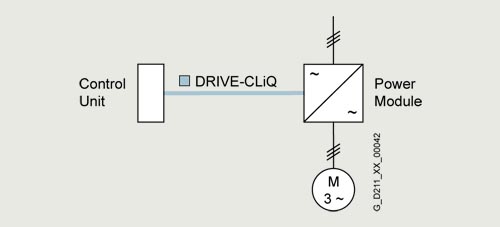
G_D211_XX_00042
Generated energy produced during braking is converted to heat in braking resistors.
The Control Unit is plugged onto the Power Module; in addition to the complete control intelligence, the Control Unit also has all the drive interfaces for communication with higher-level systems and interfacing of add-on components.
Line Modules
Line Modules contain the central line infeed for the DC link. Various Line Modules can be selected to address the various application profiles:
- Basic Line Modules
- Smart Line Modules
- Active Line Modules
Basic Line Modules
Basic Line Modules are designed only for infeed operation, i.e. they are not capable of recovering energy to the line supply. If regenerative energy is produced, e.g. when drives brake, it must be converted into heat using a Braking Module and a braking resistor.
A line filter can be optionally installed in order to ensure compliance with the limits stipulated for Category C2 in EN 61800‑3.
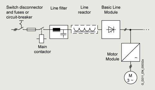
G_D211_XX_00032
Smart Line Modules
Smart Line Modules can supply energy and return regenerative energy to the supply system. A Braking Module and braking resistor are required only if the drives need to be decelerated in a controlled manner after a power failure (i.e. when energy cannot be recovered to the supply). For an infeed using a Smart Line Module, the appropriate line reactor is required.
A line filter can be optionally installed in order to ensure compliance with the limits stipulated for Category C2 in EN 61800‑3.

G_D213_XX_00033
Active Line Modules
Active Line Modules can supply energy and return regenerative energy to the supply system. A Braking Module and braking resistor are required only if the drives need to be decelerated in a controlled manner after a power failure (i.e. when energy cannot be recovered to the supply).
In contrast to Basic Line Modules and Smart Line Modules, Active Line Modules generate a controlled DC voltage that is kept constant despite fluctuations in the line supply voltage if the line supply voltage fluctuates within the permitted tolerance range. Active Line Modules in combination with an Active Interface Module draw a virtually sinusoidal current from the supply system. Almost no harmonics occur.
The total harmonic distortion factors of the current THD(I) and voltage THD(U) are typically in the range of approx. 3 % for rated current. THD(I) is calculated according to IEEE 519 (2014) and THD(U) according to IEC 61000-2-4 (2002). The stringent limit values of IEEE 519 (2014) are typically complied with.
All of the components necessary to operate an Active Line Module are integrated in the Active Interface Module.
A line filter can be optionally installed in order to ensure compliance with the limits stipulated for Category C2 in EN 61800‑3.
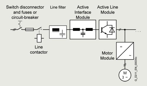
G_D211_XX_00035
Motor Modules
A voltage DC link and an inverter for supplying a motor are integrated in the Motor Module.
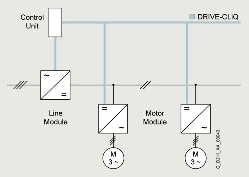
G_D211_XX_00043
Motor Modules are designed for multi-axis drive systems and are controlled by either a CU320‑2 or a SIMOTION D Control Unit. Motor Modules are interconnected through the DC link.
One or several Motor Modules are supplied with energy for the motors via the DC link. Both synchronous and induction motors can be operated.
Since the Motor Modules share the same DC link, they can exchange energy with one another, i.e. if one Motor Module operating in generator mode produces energy, the energy can be used by another Motor Module operating in motor mode. The DC link is supplied with line supply voltage by a Line Module.
Control Units
The control intelligence for all the drive axes integrated in the multi-axis group is combined in the Control Units. They also feature drive-related inputs/outputs and interfaces for communicating with higher-level controllers. Control Units are available with different ranges of functions and with different performance levels.
System components
The structure of the drive system is defined by selecting the Control Unit and Power Module or Line Module and Motor Modules. The additional components provided allow optimum adaptation of the drive system to the application.
These components are subdivided into:
-
Line-side components, e.g. line reactors and line filters
-
DC link components e.g. Braking Modules and braking resistors
-
Motor-side components, e.g. motor reactors and dv/dt filters plus VPL, sine-wave filters
-
Supplementary system components, e.g. Terminal Modules, Operator Panels, and Communication Boards
-
Encoder system interface for connecting various encoder types to SINAMICS S120
DRIVE‑CLiQ – the digital interface between the components
SINAMICS S120 components, including motors and encoders, are equipped with the high-performance DRIVE‑CLiQ system interface.
Line and Motor Modules for example are connected to the Control Unit – and Terminal Modules and Sensor Modules to the drive system via DRIVE‑CLiQ – simply and efficiently. Motors that also have this interface can be directly connected to the drive system.
Converter boards (Sensor Modules) for converting standard encoder signals to DRIVE‑CLiQ are available for third-party motors or retrofit applications.
The electronic rating plate
An important digital linkage element of the SINAMICS S120 drive system are the electronic rating plates integrated in every component. They allow all drive components to be automatically identified via the DRIVE‑CLiQ link.
The electronic rating plate contains all the relevant technical data about that particular component. In addition to the technical data, the rating plate includes logistical data (manufacturer ID, article number and ID). Since this data can be called up electronically on site or remotely, all the components used in a machine can always be individually identified, which helps simplify servicing.
Coated modules
The following devices are equipped as standard with coated modules:
- Blocksize format units
- Booksize format units
- Chassis format units
- Control Units
- Sensor Modules
- Terminal Modules
- Advanced Operator Panel (AOP30)
The coating on the modules protects the sensitive SMD components against corrosive gases, chemically active dust and moisture.
Nickel-plated busbars
All of the copper busbars used are nickel-plated in order to achieve the best possible immunity to environmental effects. Furthermore, there is no need to clean the contacts on the customer terminals as otherwise required for bare copper connections.
Note:
For some components, parts of the copper busbars cannot be nickel-plated for technical reasons.
ENG_196978.XML
Communication with higher-level controller and customer terminal strip
As customer interface to a higher-level control, as standard there is a PROFIBUS or PROFINET communication interface on the Control Unit CU320-2; there are also expansions such as the Terminal Module TM31, the Terminal Board TB30 and modules to communicate via CANopen or EtherNet/IP.
These interfaces can be used to connect the system to the higher-level controller using analog and digital signals, or to connect additional units.
For additional information, please refer to the SINAMICS Low Voltage Engineering Manual.
Open-loop and closed-loop control functions
SINAMICS S120 can use a dynamic, high-precision closed-loop vector control (drive object type VECTOR), or a highly dynamic closed-loop servo control (drive object type SERVO).
Software and protective functions
The software functions available as standard are described below:
|
Software and protective functions
|
Description
|
|
Setpoint input
|
The setpoint can be specified both internally and externally; internally as a fixed setpoint, motorized potentiometer setpoint or jog setpoint, externally via the communications interface or an analog input. The internal fixed setpoint and the motorized potentiometer setpoint can be switched or adjusted via control commands from any interface.
|
|
Motor identification
|
The automatic motor identification function makes commissioning faster and easier and optimizes closed-loop control of the drive.
|
|
Ramp-function generator
|
A user-friendly ramp-function generator with separately adjustable ramp-up and ramp-down times, together with adjustable rounding times in the lower and upper speed ranges, allows the drive to be smoothly accelerated and braked. This results in a good speed control response and contributes to the reduction of stress on the mechanical system. The down ramp can be parameterized separately for a quick stop.
|
|
Vdc max controller
|
The Vdc max controller automatically prevents overvoltages in the DC link, if the set down ramp is too short, for example. This may also extend the set ramp-down time.
Note: This function only makes sense for single-axis applications.
|
|
Kinetic buffering (KIP)
|
For brief line supply failures, the kinetic energy of the rotating drive is used to buffer the DC link and therefore prevents fault trips. The converter remains operational as long as the drive can provide regenerative energy as a result of its motion and the DC link voltage does not drop below the shutdown threshold. When the line supply recovers within this time, the drive is again bumplessly accelerated up to its setpoint speed.
|
|
Automatic restart
|
The automatic restart switches the drive on again when the power is restored after a power failure, and ramps up to the current speed setpoint.
|
|
Flying restart
|
The flying restart function allows the converter to be switched to a motor that is still turning. With the voltage sensing capability provided by the optional VSM10, the flying restart time for large induction motors can be significantly reduced because the motor does not need to be de-magnetized.
|
|
Technology controller (PID)
|
Using the technology controller (PID controller) function module, level or flow controls and complex tension controls can be implemented, for example. The existing D component can act both on the system deviation as well as on the actual value (factory setting). The P, I, and D components are set separately.
|
|
Free function blocks (FFB)
|
Using the freely programmable function blocks, it is easy to implement logic and arithmetic functions for controlling the SINAMICS drive. The blocks can be programmed at the operator panel or the STARTER commissioning tool.
|
|
Drive Control Chart (DCC)
|
Drive Control Chart (DCC) is an additional tool for the easy configuration of technological functions for SINAMICS. The block library contains a large selection of control, arithmetic and logic blocks as well as extensive open-loop and closed-loop control functions. The user-friendly DCC editor enables easy graphics-based configuration, allows control loop structures to be clearly represented and provides a high degree of reusability of charts that have already been created. DCC is an add-on for the STARTER commissioning tool (see Tools and engineering).
|
|
SINAMICS Technology Extensions (SINAMICS TEC)
|
The SINAMICS TEC are configurable functions or Siemens technologies that can be added to extend firmware functions. These extensions are designed to allow implementation of highly complex, application-specific tasks for various sectors - such as storage and retrieval machines.
Additional information about Technology Extensions (TEC) is provided in the "Technology functions" section.
|
|
I2t sensing for motor protection
|
A motor model stored in the converter software calculates the motor temperature based on the current speed and load. More exact measurement of the temperature, which also takes into account the influence of the ambient temperature, is possible by means of direct temperature measurement using Pt100/KTY84 sensors in the motor winding.
|
|
Motor temperature evaluation
|
Motor protection by evaluating a KTY84, PTC, Pt100 or Pt1000 temperature sensor. When a KTY84 temperature sensor is connected, the limit values can be set for alarm or shutdown. When a PTC thermistor is connected, the system reaction to triggering of the thermistor (alarm or trip) can be defined.
|
|
Motor blocking protection
|
A blocked motor is detected and protected against thermal overloading by a fault trip.
|
|
Brake control
|
"Simple brake control" for control of holding brakes:
The holding brake is used to secure drives against unwanted motion when deactivated.
"Extended brake control" function module for complex brake control, e.g. for motor holding brakes and operational brakes:
When braking with a feedback signal, the brake control reacts to the feedback signal contacts of the brake.
|
|
Write protection
|
Write protection to prevent unintentional changing of the setting parameters (without password function).
|
|
Know-how protection
|
Know-how protection for encrypting stored data, e.g. to protect configuration know-how, and to protect against changes and duplication (with password function).
|
|
Web server
|
The web server provides information about the drive unit via its web pages. The web server is accessed using a web browser via unsecured (http) or secured transfer protocol (https).
|
Power unit protection
|
Power unit protection
|
Description
|
|
Ground fault monitoring at the output
|
A ground fault at the output is detected by a total current monitor and results in shutdown in grounded systems.
|
|
Electronic short-circuit protection at the output
|
A short-circuit at the output (e.g. at the converter output terminals, in the motor cable or in the motor terminal box) is detected and the converter shuts down with a "fault".
|
|
Thermal overload protection
|
An alarm is issued first when the overtemperature threshold responds. If the temperature continues to rise, the unit either shuts down or independently adjusts the pulse frequency or output current so that thermal load is reduced. Once the cause of the fault has been eliminated (e.g. cooling has been improved), the original operating values are automatically resumed.
|
