ENG_439390.XML

G_PA10_XX_00372
D-R 290 system components
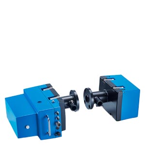
Measuring device
The transmitter and receiver optics are integrated together with the electronics to form a compact unit housed within a rugged and robust aluminum enclosure. The measuring device is mounted on the weld-in flange.
Reflector
The reflector is installed in a rugged and robust aluminum housing. The reflector is mounted on the weld-in flange directly opposite the measuring device.
Software D‑ESI 100
Parameterization software, visualization of the measured data and performance of maintenance functions.
The device can be parameterized, maintained and, in the event of a fault, analyzed via the USB port with the help of a Windows PC and the associated software D‑ESI 100.
Purge air unit
A hose connects the measuring device and the reflector with the purge air unit. The filtered air is used to keep the scattered light interfaces of the measuring device and the reflector clean.
Terminal box
Terminal box to output the data with connecting cable for the measuring device and customer terminal strips.
Optional
Universal control unit D-ISC 100
Up to eight connected devices can be easily configured and operated using the D‑ISC 100 control unit. The display provides an immediate overview of the current measured values and the status of the measuring instruments.
Quick-closing shutters
The quick-closing shutters are mounted on the measuring device and the reflector side between the weld-in flanges and the connected devices (measuring device, reflector). In the event of a fault (failure of the power supply or purge air), they automatically close the path between the exhaust gas duct and the measuring equipment.
Electronics for quick-closing shutter
A control electronics system is required for each quick-closing shutter.
Measured value acquisition
In the simplest case the measured values and reference values are transferred to the plant's control system. The measured values and status signals that are output can also be fed into an emission calculator system for further processing. Either via discrete signals (4 to 20 mA and configurable relay contacts) or via Modbus according to VDI 4201‑3.
Weather protection covers
Weather protection covers are available to protect the measuring device, the reflector, the purge air unit and the junction boxes when the measuring system is installed outdoors.
Additional options
- Explosion-proof device design for Ex p, Zone 1 or Zone 2, 22
- Filter set for sensitivity and linearity control
ENG_439391.XML
The device operates using the double-pass method according to the auto-collimation principle. The light beam traverses the measuring distance twice. The attenuation of the light beam by the dust content in the measuring section is measured and evaluated.
By means of a gravimetric reference calibration, a calibration curve can be stored on the integrated electronics and the measured signal can be converted into a dust concentration in mg/m³.