ENG_439452.XML

G_PA10_XX_00376
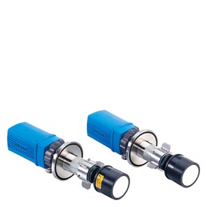
D‑FL 220 system components
Measuring devices
Two identically designed measuring devices are used. Depending on the application data, different depth-of-penetration lengths are required, for example, from 100 to 1 100 mm.
A 4 to 20 mA current signal is available as measured value output which is proportional to the speed and/or the volume flow and can be connected, for example, to a emission evaluation calculator. Two relay contacts are available for signaling. Also available is a Modbus interface according to VDI 4201‑3 for the connection of an emission evaluation calculator with digital interface. The various parameters are entered during the installation on site. The USB port is on the rear.
Purge air flange
The purge air is supplied to each of the two measuring heads via a purge air flange for cooling and cleaning the ultrasonic transducers. A toggle-type fastener connects the purge air flange to the measuring device.
Mounting tubes with flange
Mounting tubes made of stainless steel 1.4571 or of glass-fiber reinforced plastic, adapted to the plant conditions, are available.
Purge air unit
A hose connects the two measuring devices to the purge air unit. The filtered air is used to cool the measuring devices and to keep the transmitters clean.
Terminal box
Terminal box to output the data with connecting cable for the two sensors and customer terminal strip.
Software D‑ESI 100
Parameterization software, visualization of the measured data and performance of maintenance functions.
The device can be parameterized, maintained and, in the event of a fault, analyzed via the USB port with the help of a PC and the associated software D‑ESI 100.
Optional
Universal control unit D‑ISC 100
The connected devices can be easily configured and operated using the D‑ISC 100 control unit. The display provides an immediate overview of the current measured values and the status of the measuring instruments.
Measured value acquisition
In the simplest case the measured values and reference values are transferred to the plant's control system. The measured values and status signals that are output can also be fed into an emission calculator system for further processing. Either via discrete signals (4 to 20 mA and configurable relay contacts) or via Modbus according to VDI 4201‑3.
Weather protection covers
Weather protection covers are available to protect the measuring heads when the measuring system is installed outdoors.
Additional options
- Absolute pressure transmitter
- Temperature transmitter
ENG_439453.XML
The D-FL 220 measuring system operates according to the acoustic transit time differential method.
Two identical sensors transmit and receive ultra-sonic pulses reciprocally. The system calculates precisely the gas velocity and the gas temperature from the transit time difference dependent on the direction. The volume flow is calculated taking into consideration the cross-section, the sample gas temperature and the absolute pressure. The D-FL 220 performs internal self-monitoring routines and is very low maintenance.