ENG_495596.XML
Line Modules
Power is fed to the drive line-up via Line Modules, which generate a DC voltage from the line voltage and, therefore, supply energy to the Motor Modules connected to the DC link. They are suitable for connection to grounded TN/TT and non-grounded IT systems.
The Line Modules are connected to the line supply system via Line Connection Modules and are equipped as standard according to Category C3. Category C3 is part of the "second environment" (in accordance with EN 61800-3). The “second environment” constitutes locations outside residential areas or industrial sites which are supplied from the medium-voltage network via a separate transformer.
The range of Line Modules has power ratings from 132 kW to 900 kW (380 V to 480 V) and from 250 kW to 1500 kW (500 V to 690 V). Furthermore, up to four identical Line Modules can be connected in parallel in order to increase the power rating.
For a compact configuration, Line Connection Modules up to input currents of 3200 A are available. Two Line Modules can be operated in parallel on these Line Connection Modules.
The following types of Line Modules are available:
- Basic Line Modules
- Smart Line Modules
- Active Line Modules
Basic Line Modules
Basic Line Modules are designed only for infeed operation, i.e. they are not capable of recovering energy to the line supply.
If regenerative energy is produced, e.g. when the drives brake, then it must be converted to heat by means of a Braking Module and a braking resistor.
When a Basic Line Module is used as the infeed, a line reactor appropriate to the supply conditions must be installed. Line reactors are generally required if two or more Basic Line Modules are operated in parallel on a common supply system in order to increase power.
For this reason, line reactors are installed in the appropriate Line Connection Module as standard.
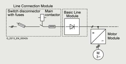
G_D213_XX_00042
Line Connection Module with Basic Line Module ≤800 A
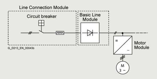
G_D213_XX_00043
Line Connection Module with Basic Line Module >800 A
If, for example, a converter transformer is used to connect to the line supply (12-pulse operation), it may be possible to omit line reactors (depending on the supply conditions on site) and they can be optionally deselected (option L22 for a Line Connection Module combined with a Basic Line Module).
For a compact configuration, Line Connection Modules with input currents of up to 3200 A are available. Two Basic Line Modules can be operated in parallel on these Line Connection Modules. Versions with line-side fuses are available for parallel connections in order to provide selective protection of the individual Basic Line Modules.
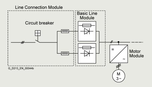
G_D213_XX_00044
Line Connection Module with Basic Line Modules connected in parallel
Smart Line Modules
Smart Line Modules can supply energy to the DC link and return regenerative energy to the supply system. A Braking Module and braking resistor are required only if the drives need to be decelerated in a controlled manner after a power failure (i.e. when energy cannot be recovered to the supply). When a Smart Line Module is used as the infeed, the necessary line reactor is included in the device as standard and can be optionally deselected (option L22).

G_D213_XX_00045
Line Connection Module with Smart Line Module ≤800 A
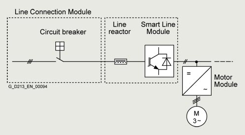
G_D213_XX_00094
Line Connection Module with Smart Line Module >800 A

G_D213_XX_00095
Line Connection Module with Smart Line Modules connected in parallel
Active Line Modules
Active Line Modules can supply energy to the DC link and return regenerative energy to the supply system. A Braking Module and braking resistor are required only if the drives need to be decelerated in a controlled manner after a power failure (i.e. when energy cannot be recovered to the supply).
In contrast to Basic Line Modules and Smart Line Modules, however, Active Line Modules generate a regulated DC voltage which remains constant despite fluctuations in the line voltage. However, in this case, the line voltage must remain within the permissible tolerance range. Active Line Modules in combination with an Active Interface Module draw a virtually sinusoidal current from the supply system. Almost no harmonics occur. The total harmonic distortion factors of the current THD(I) and voltage THD(U) are typically in the range of approx. 3 % for rated current. THD(I) is calculated according to IEEE 519 (2014) and THD(U) according to IEC 61000-2-4 (2002). The stringent limit values of IEEE 519 (2014) are typically complied with.
Active Line Modules must always be used in conjunction with an Active Interface Module. Active Interface Modules include the required pre-charging circuit for the Active Line Module in addition to a Clean Power Filter. For SINAMICS S120 Cabinet Modules, these two components are always regarded as a single unit.

G_D213_XX_00046
Line Connection Module with Active Interface Module and Active Line Module ≤ 800 A (example frame size HX + HI)

G_D213_XX_00047
Line Connection Module with Active Interface Module and Active Line Module >800 A
In the example, two units comprising an Active Interface Module and Active Line Module are connected in parallel to jointly supply the DC link.
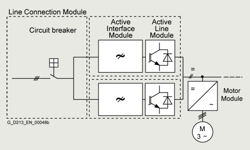
G_D213_XX_00048
Line Connection Module with Active Interface Modules and Active Line Modules connected in parallel
DC link components
Braking Modules enable braking resistors to absorb the regenerative energy produced during drive deceleration, which is then converted into heat. Using a Braking Module and a braking resistor, it is possible to brake motors even when the power fails.
Braking Modules as a Line Module or Motor Module option
For lower braking powers, Braking Modules are available with continuous braking powers up to 50 kW. These Braking Modules are ordered as an option for the Line Modules and Motor Modules (order codes L61/L64 (25 kW) or L62/L65 (50 kW), refer to the option description).
Central Braking Modules
For higher continuous braking powers, separate Central Braking Modules are available. These modules are used centrally in the drive line-up. To increase the braking power, up to four Central Braking Modules can be connected in parallel in the drive line-up.
Motor Modules
There are two different types of Motor Modules available with the SINAMICS S120 Cabinet Modules drive system.
Booksize Base Cabinets with Booksize Cabinet Kits
Motor Modules at the low end of the power range from 4.8 kW to 71 kW (380 V to 480 V) can be implemented as Booksize Cabinet Kits installed in Booksize Base Cabinets.
Chassis Cabinets
Each Chassis Cabinet is fitted with one SINAMICS S120 Motor Module in chassis format and covers the power range from 75 kW to 1200 kW (380 V to 480 V or 500 V to 690 V). The power rating can be extended up to approx. 4500 kW by connecting up to four Motor Modules in chassis format in parallel.
SINAMICS S120 Motor Modules in chassis format can also be used as Braking Modules (braking choppers) if a 3-phase braking resistor is connected instead of a motor.
For more information on this topic, please refer to the SINAMICS Low Voltage Engineering Manual.
Auxiliary Power Supply Modules
Auxiliary Power Supply Modules supply power to the auxiliary power supply system of the SINAMICS S120 Cabinet Modules.
Units connected to this auxiliary power supply system include the fans of the SINAMICS S120 devices installed in the Cabinet Modules. In addition, the auxiliary power supply system supplies the electronic modules with an external 24 V DC voltage. This is required when the DC link is not charged, for instance, in order to maintain PROFIBUS or PROFINET communication.
ENG_495598.XML
Derating data for the chassis format
SINAMICS S120 Cabinet Modules and the associated system components are rated for an ambient temperature of 40 °C and installation altitudes up to 2000 m above sea level.
At ambient temperatures > 40 °C, the output current must be reduced. Ambient temperatures above 50 °C are not permissible.
At installation altitudes > 2000 m above sea level, it must be taken into account that the air pressure, and therefore air density, decreases as the height increases. As a consequence, the cooling efficiency and the insulation capacity of the air also decrease.
Due to the reduced cooling efficiency, it is necessary to both reduce the ambient temperature and lower heat loss in the Cabinet Module by reducing the output current, whereby ambient temperatures lower than 40 °C may be offset to compensate.
The following table specifies the permissible output currents as a function of the installation altitude and ambient temperature for the various degrees of protection. (The permissible compensation between installation altitude and the ambient temperatures < 40 °C – air intake temperature at the entry to the Cabinet Module – has been taken into account in the specified values.)
The values apply under the precondition that it is guaranteed that the cooling air, as specified in the technical data, flows through the units as a result of the cabinet arrangement.
As an additional measure for installation altitudes from 2000 m up to 5000 m, an isolating transformer is required in order to reduce transient overvoltages according to EN 60664‑1.
For additional information, please refer to the SINAMICS Low Voltage Engineering Manual.
Current-derating factors for Cabinet Modules as a function of the ambient/air intake temperature, the installation altitude and the degree of protection
|
Degree of protection
|
Installation altitude above sea level
|
Current derating factor (as a percentage of the rated current)
for an ambient/air intake temperature of
|
|
|
m (ft)
|
20 °C (68 °F)
|
25 °C (77 °F)
|
30 °C (86 °F)
|
35 °C (95 °F)
|
40 °C (104 °F)
|
45 °C (113 °F)
|
50 °C (122 °F)
|
|
IP20, IP21, IP23, IP43
|
0 ... 2000 (0 ... 6562)
|
100 %
|
100 %
|
100 %
|
100 %
|
100 %
|
93.3 %
|
86.7 %
|
|
2001 ... 2500 (6565 ... 8202)
|
100 %
|
100 %
|
100 %
|
100 %
|
96.3 %
|
|
|
|
2501 ... 3000 (8205 ... 9843)
|
100 %
|
100 %
|
100 %
|
98.7 %
|
|
|
|
|
3001 ... 3500 (9846 ... 11483)
|
100 %
|
100 %
|
100 %
|
|
|
|
|
|
3501 ... 4000 (11486 ... 13123)
|
100 %
|
100 %
|
96.3 %
|
|
|
|
|
|
4001 ... 4500 (13127 ... 14764)
|
100 %
|
97.5 %
|
|
|
|
|
|
|
4501 ... 5000 (14767 ... 16404)
|
98.2 %
|
|
|
|
|
|
|
|
IP54
|
0 ... 2000 (0 ... 6562)
|
100 %
|
100 %
|
100 %
|
100 %
|
93.3 %
|
86.7 %
|
80 %
|
|
2001 ... 2500 (6565 ... 8202)
|
100 %
|
100 %
|
100 %
|
96.3 %
|
89.8 %
|
|
|
|
2501 ... 3000 (8205 ... 9843)
|
100 %
|
100 %
|
98.7 %
|
92.5 %
|
|
|
|
|
3001 ... 3500 (9846 ... 11483)
|
100 %
|
100 %
|
94.7 %
|
|
|
|
|
|
3501 ... 4000 (11486 ... 13123)
|
100 %
|
96.3 %
|
90.7 %
|
|
|
|
|
|
4001 ... 4500 (13127 ... 14764)
|
97.5 %
|
92.1 %
|
|
|
|
|
|
|
4501 ... 5000 (14767 ... 16404)
|
93 %
|
|
|
|
|
|
|
Current derating for SINAMICS S120 Motor Modules, chassis format as a function of the pulse frequency
To reduce motor noise or to increase output frequency, the pulse frequency can be increased relative to the factory setting (1.25 kHz or 2 kHz). When the pulse frequency is increased, the derating factor of the output current must be taken into account. This derating factor must be applied to the currents specified in the technical specifications.
For additional information, please refer to the SINAMICS Low Voltage Engineering Manual.
Derating factor of the output current as a function of the pulse frequency for units with a rated pulse frequency of 2 kHz
|
Motor Module in chassis format
|
Type rating
at 400 V
|
Output current
at 2 kHz
|
Derating factor
at pulse frequency
|
|
6SL3720-...
|
kW
|
A
|
2.5 kHz
|
4 kHz
|
5 kHz
|
7.5 kHz
|
8 kHz
|
|
380 ... 480 V 3 AC
|
|
1TE32-1AA3
|
110
|
210
|
95 %
|
82 %
|
74 %
|
54 %
|
50 %
|
|
1TE32-6AA3
|
132
|
260
|
95 %
|
83 %
|
74 %
|
54 %
|
50 %
|
|
1TE33-1AA3
|
160
|
310
|
97 %
|
88 %
|
78 %
|
54 %
|
50 %
|
|
1TE33-8AA3
|
200
|
380
|
96 %
|
87 %
|
77 %
|
54 %
|
50 %
|
|
1TE35-0AA3
|
250
|
490
|
94 %
|
78 %
|
71 %
|
53 %
|
50 %
|
Derating factor of the output current as a function of the pulse frequency for units with a rated pulse frequency of 1.25 kHz
|
Motor Module in chassis format
|
Type rating
at 400 V or 690 V
|
Output current
at 1.25 kHz
|
Derating factor
at pulse frequency
|
|
6SL3720-...
|
kW
|
A
|
2 kHz
|
2.5 kHz
|
4 kHz
|
5 kHz
|
7.5 kHz
|
8 kHz
|
|
380 ... 480 V 3 AC
|
|
|
1TE36-1AA3
|
315
|
605
|
83 %
|
72 %
|
64 %
|
60 %
|
40 %
|
36%
|
|
1TE37-5AA3
|
400
|
745
|
83 %
|
72 %
|
64 %
|
60 %
|
40 %
|
36%
|
|
1TE38-4AA3
|
450
|
840
|
87 %
|
79 %
|
64 %
|
55 %
|
40 %
|
37 %
|
|
1TE41-0AA3
|
560
|
985
|
92 %
|
87 %
|
70 %
|
60 %
|
50 %
|
47 %
|
|
1TE41-2AA3
|
710
|
1260
|
92 %
|
87 %
|
70 %
|
60 %
|
50 %
|
47 %
|
|
1TE41-4AA3
|
800
|
1405
|
97 %
|
95 %
|
74 %
|
60 %
|
50 %
|
47 %
|
|
500 ... 690 V 3 AC
|
|
|
1TG28-5AA3
|
75
|
85
|
93 %
|
89 %
|
71 %
|
60 %
|
40 %
|
-
|
|
1TG31-0AA3
|
90
|
100
|
92 %
|
88 %
|
71 %
|
60 %
|
40 %
|
-
|
|
1TG31-2AA3
|
110
|
120
|
92 %
|
88 %
|
71 %
|
60 %
|
40 %
|
-
|
|
1TG31-5AA3
|
132
|
150
|
90 %
|
84 %
|
66 %
|
55 %
|
35 %
|
-
|
|
1TG31-8AA3
|
160
|
175
|
92 %
|
87 %
|
70 %
|
60 %
|
40 %
|
-
|
|
1TG32-2AA3
|
200
|
215
|
92 %
|
87 %
|
70 %
|
60 %
|
40 %
|
-
|
|
1TG32-6AA3
|
250
|
260
|
92 %
|
88 %
|
71 %
|
60 %
|
40 %
|
-
|
|
1TG33-3AA3
|
315
|
330
|
89 %
|
82 %
|
65 %
|
55 %
|
40 %
|
-
|
|
1TG34-1AA3
|
400
|
410
|
89 %
|
82 %
|
65 %
|
55 %
|
35 %
|
-
|
|
1TG34-7AA3
|
450
|
465
|
92 %
|
87 %
|
67 %
|
55 %
|
35 %
|
-
|
|
1TG35-8AA3
|
560
|
575
|
91 %
|
85 %
|
64 %
|
50 %
|
35 %
|
-
|
|
1TG37-4AA3
|
710
|
735
|
87 %
|
79 %
|
64 %
|
55 %
|
35 %
|
-
|
|
1TG38-1AA3
|
800
|
810
|
97 %
|
95 %
|
71 %
|
55 %
|
35 %
|
-
|
|
1TG38-8AA3
|
900
|
910
|
92 %
|
87 %
|
67 %
|
55 %
|
33 %
|
-
|
|
1TG41-0AA3
|
1000
|
1025
|
91 %
|
86 %
|
64 %
|
50 %
|
30 %
|
-
|
|
1TG41-3AA3
|
1200
|
1270
|
87 %
|
79 %
|
55 %
|
40 %
|
25 %
|
-
|
Maximum output frequencies achieved by increasing the pulse frequency
The adjustable pulse frequencies – and therefore the output frequencies that can be achieved with the factory-set current controller clock cycles – are listed below.
|
Current controller clock cycle
TI
|
Adjustable pulse frequency
fp
|
Max. achievable output frequency fA
|
|
V/f mode
|
Vector mode
|
Servo mode
|
|
250 µs 1)
|
2 kHz
|
166 Hz
|
166 Hz
|
333 Hz
|
|
4 kHz
|
333 Hz
|
333 Hz
|
550 Hz 3)
|
|
8 kHz
|
550 Hz 3)
|
480 Hz
|
550 Hz 3)
|
|
400 µs 2)
|
1.25 kHz
|
104 Hz
|
104 Hz
|
–
|
|
2.5 kHz
|
208 Hz
|
208 Hz
|
–
|
|
5.0 kHz
|
416 Hz
|
300 Hz
|
–
|
|
7.5 kHz
|
550 Hz 3)
|
300 Hz
|
–
|
1) As factory setting, the following Motor Modules in chassis format have a current controller clock cycle of 250 µs and a pulse frequency of 2 kHz: - 510 ... 720 V DC: ≤ 250 kW / 490 A
2) As factory setting, the following Motor Modules in chassis format have a current controller clock cycle of 400 µs and a pulse frequency of 1.25 kHz: - 510 ... 720 V DC: ≥ 315 kW / 605 A- 675 ... 1035 V DC: All power ratings
3) With the "High output frequencies" license, which can be ordered as option J01 on the CompactFlash card for SINAMICS S120, the maximum output frequency is increased up to 650 Hz. For more information, see https://support.industry.siemens.com/cs/document/104020669
Derating data for devices in booksize format
SINAMICS S120 Cabinet Modules with power units in booksize format and the associated system components are rated for an ambient temperature of 40 °C and installation altitudes up to 1000 m above sea level. If SINAMICS S120 Cabinet Modules with power units in booksize format are operated at ambient temperatures higher than 40 °C and/or installation altitudes higher than 1000 m above sea level, then the corresponding derating factors must be taken into account as a function of the ambient temperature and/or the installation altitude. These derating factors are different from the derating factors for the chassis format power units and are listed in Catalog D 21.4.
Overload capability
SINAMICS S120 Cabinet Modules have an overload reserve, e.g. to handle breakaway torques. If larger surge loads occur, this must be taken into account in the configuration. For drives with overload requirements, the appropriate base load current must, therefore, be used as a basis for the required load.
Permissible overload assumes that the converter is operated at its base-load current before and after the overload occurs, based on a duty cycle duration of 300 s.
Another precondition is that the Motor Modules are operated at their factory-set pulse frequency at output frequencies >10 Hz.
For temporary, periodic duty cycles with high variations of load within the duty cycle, the relevant sections of the SINAMICS Low Voltage Engineering Manual must be observed.
Motor Modules in chassis format
Motor Modules with power units in chassis format can be configured on the basis of different base load currents.
The base-load current for a low overload IL is the basis for a duty cycle of 110 % for 60 s or 150 % for 10 s.

G_D213_XX_00035
Low overload
The base-load current IH for a high overload is based on a load cycle of 150 % for 60 s or 160 % for 10 s.

G_D213_XX_00036
High overload
Motor Modules in booksize format
Motor Modules with power units in the booksize format have the following overload capabilities:
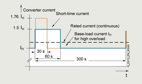
G_D213_XX_00049
High overload
Line Modules in chassis format
The base-load current for a high overload IH DC is the basis for a duty cycle of 150 % for 60 s or Imax DC for 5 s.

G_D213_XX_00079
