ENG_822076.xml
The gas analyzer LDS 6 consists of a central unit and up to three in-situ optics enclosures. The connection between the central unit and the optics enclosures is established by a so-called hybrid cable, which contains fiber-optic cables and copper wires. An additional sensor cable connects the transmitter and receiver parts of the optics enclosure.
Central unit
The central unit is housed in a 19" rack unit housing with 4 mounting points
- in a hinged frame
- in racks with or without telescopic rails
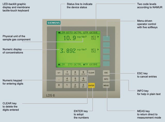
Display and operator panel
- Large LCD field for simultaneous display of measurement result and device status
- Contrast of the LCD display is adjustable via the menu
- LED backlight of the display with energy-saving function
- Easy-to-clean membrane touch pad with softkeys
- Menu-driven operation for parameterization and diagnostics
- Operation support in plain text
Inputs and outputs
- One to three measurement channels with hybrid cable connections for the optics enclosure at the measuring points
- 2 analog inputs per channel for process gas temperature and pressure
- 2 analog outputs per channel for gas concentration(s). For selected versions, the transmission can be read out as an alternative.
- 6 freely configurable digital inputs per channel for signaling faults or maintenance demanded from external temperature or pressure transducers or insufficient purging of the optics enclosure.
- 6 freely configurable digital outputs per channel (signaling of errors, maintenance required, function control, transmission limit alarm, concentration limit alarm, store analog output)
Communication
Network connection: Ethernet (T-Base-10) for remote diagnostics and maintenance.
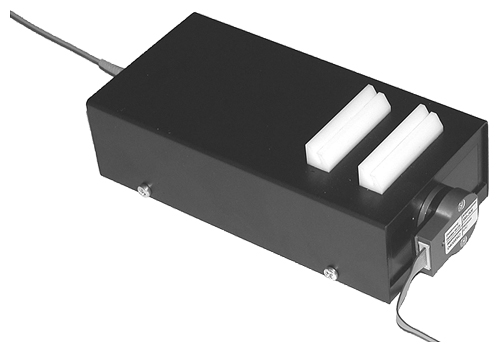
G_PA10_XX_00083
LDS 6 central unit, membrane keyboard and graphic display
Optics enclosure
P_PA10_XX_00029
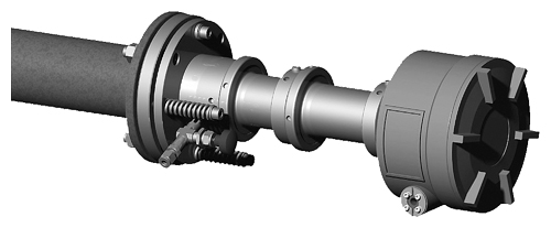
Optics enclosure CD 6, transmitter or detector unit
- In-situ optics enclosure, configured as transmitter and detector unit, connected via sensor cable
- Connection to the LDS 6 central unit via a so-called hybrid cable of max. 700 m length (total hybrid and sensor connecting cable length: max. 250 m in hazardous zone 0 and hazardous zone 1)
- Stainless steel, some painted aluminum
- Optics enclosure according to IP65 degree of protection
- Adjustable flanges with flange connection
- DN 65/PN 6, ANSI 4"/150 lbs
- Optional flameproof window flanges with dimensions: DN 65/PN 6, DN 80/PN 16, ANSI 4"/150 lbs, other process interfaces available on request
- Purging facilities on the process and the sensor sides, configurable application with purging gas connections for:
- Instrument air
- Purging air blower
- Steam
- Nitrogen
- Process gases to which the pressure equipment directive Cat. 2 does not apply
- In combination with high-pressure window flanges, purging can be performed on the process side with instrument air or nitrogen
- Quick release fasteners for cleaning the measurement openings and the optics enclosure window
- Optional: Version with explosion protection in accordance with ATEX / IEC Ex ia
- Optics enclosure CD 6 is compliant with the pressure equipment directive
Parts in contact with the process gas
The optics enclosure normally does not come into contact with the process gas, since purging with a gaseous medium is applied at the process side. Stainless steel or propylene (PP) purging gas tubes in front of the sensor windows are immersed slightly into the process gas and thus limit the purging volume. Special materials such as Hastelloy are available on request.
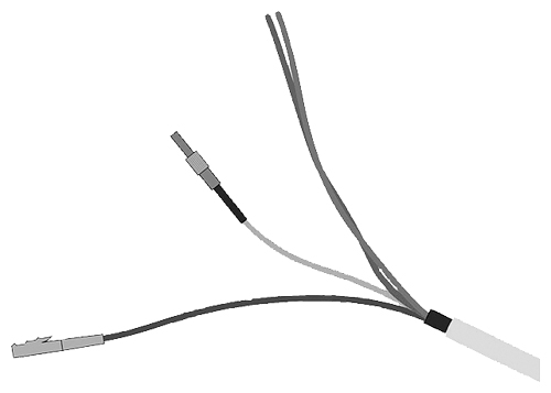
Hybrid and sensor cables
A combination of fiber-optic cables and twisted copper wires connects the optics enclosure to the central unit. The hybrid cable connects the central unit with the detector unit of the optics enclosure, the sensor cable connects the transmitter and detector unit of the optics enclosure.
For installation in Ex-protected environments, the legislative regulations have to be complied with, such as the spatial separation of intrinsically safe from non-intrinsically safe cables.
In compliance with standard EN IEC 60079-14, systems with intrinsically safe circuits must be installed such that their intrinsic safety is not impaired by electric or magnetic fields. Therefore the hybrid and sensor cables of the LDS 6 in an Ex application must be routed in such a way that they cannot generate electric or magnetic fields, e.g. by coiling them in more than one cable loop. To guarantee a good signal quality and to avoid impermissible inductance loops, the hybrid and sensor cables should be kept as short as possible.
- The distance between central unit and measuring point can be
- up to 250 m for Ex devices when used in Zone 0 and Zone 1 (total hybrid and sensor connecting cable length)
- up to 700 m for Ex devices used in Zone 2 and for non-Ex devices
- Hybrid and sensor cables
- Multimode fiber-optic cable, provided with SMA connections for transmission of the measured signal
- Two-wire copper cable, in twisted pair version, for (+24 V) power supply of the detector electronics (+12 V in the case of Ex-suitable instruments)
- Additionally for the hybrid cable:
- Single-mode fiber-optic cable, configured double-sided with E2000 connectors for transmission of laser light
- Rugged cable jacket for laying in open cable ducts or ductworks
- Sheath material: oil-resistant polyurethane
P_PA10_XX_00031
Connections of the hybrid cable
ENG_822075.xml
Operating principle
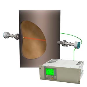
LDS 6 is a gas analyzer employing single-line molecular absorption spectroscopy. A diode laser emits a beam of near-infrared light, which passes through the process gas and is detected by a detector unit. The wavelength of the laser diode output is tuned to a gas-specific absorption line. The laser continuously scans this single absorption line with a very high spectral resolution. The result is a fully resolved single molecular line which is analyzed in terms of absorption strength and line shape. The influence of cross-sensitivities on the measurement is negligible, since the quasi-monochromatic laser light is absorbed very selectively by only one specific molecular line in the scanned spectral range.
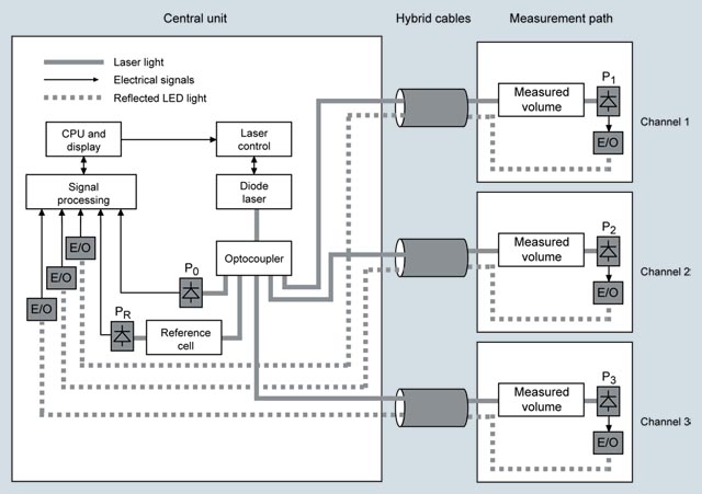
G_PA10_XX_00096
Basic design of the LDS 6
Configuration examples:
A feature of the in-situ analytical procedure is that the physical measurement takes place directly in the process gas stream, and usually also directly in the actual process gas line. All process parameters such as gas matrix, pressure, temperature, moisture, dust load, flow velocity and mounting orientation can influence the measuring properties of the LDS 6 and must therefore be systematically investigated for each new application.
A feature of the standard applications defined in the ordering data of the LDS 6 is that the typical process conditions are well-known, documented, and the guaranteed measuring properties can be proven by reference installations. If you cannot find your application among the standard applications, please contact Siemens. We will be pleased to check your possible individual application of the LDS 6. You can find an application questionnaire on the LDS 6 product pages on the internet:
www.siemens.com/insituquestionnaire
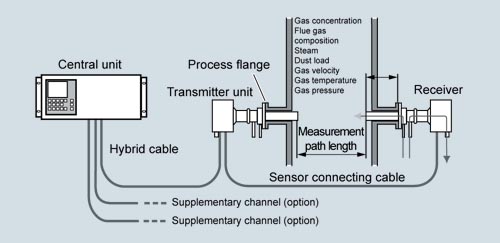
G_PA10_XX_00126
Typical transmitted light setup of LDS 6, in situ
To avoid contamination of optics on the process side, clean gaseous purging media such as instrument air, N2 or steam are used. Purging air tubes on the optics enclosures, which slightly penetrate into the process gas stream, define the effective measuring path length.
The LDS 6 can measure in both the transverse and longitudinal directions of the process gas flow. In certain cases, the process conditions make it necessary to condition the sample gas stream in a bypass line with respect to process temperature, pressure and/or optical path length. Further treatment of the process gas, such as drying or dust precipitation, is usually unnecessary.
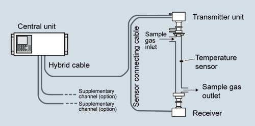
G_PA10_XX_00124
Typical transmitted light setup of LDS 6, in bypass
A flow cell is available by special application for the LDS 6 which has been specially optimized for use with the LDS 6 and its optics enclosures with respect to handling and measuring performance. It is designed to reduce surface effects, and is therefore also highly suitable for polar gases like ammonia. This flow cell is available in heated and non-heated versions. Wheel mounted and wall mounted versions are available.
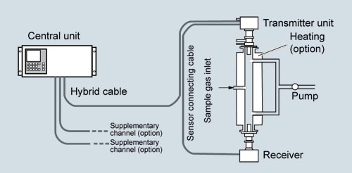
G_PA10_XX_00125
Measuring configuration of LDS 6 with heated flow cell
General information
LDS 6 is connected to the measuring points by fiber optics. The laser light is guided by a single-mode fiber from the central unit to the transmitter unit of the in-situ optics enclosure. The optics enclosure consists of a transmitter and a detector. The distance between them defines the measurement path. In the detector, the light is focused onto a suitable detector. The detector signal is then converted into an optical signal and transmitted via a second optical fiber to the central unit, where the concentration of the gas component is determined from the detected absorption signal.
LDS 6 usually measures a single gas component by means of the absorption capacity of a single fully resolved molecular absorption line. The absorption results from conversion of the radiation energy of the laser light into the internal energy of the molecule.
In some specific cases, two components can be measured simultaneously if their absorption lines are so close to each other that they can be detected within the laser spectrum by one single sampling (for example water (H2O) and ammonia (NH3)).
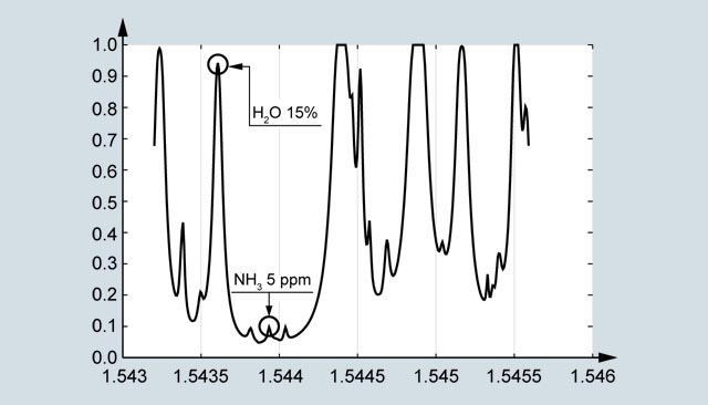
G_PA10_XX_00090
Absorption spectra of water and ammonia
Typical measurable gases for LDS 6 are:
- Hydrogen fluoride (HF) + water
- Hydrogen chloride (HCl) + water
- Ammonia (NH3) + water
- Water vapor (H2O)
- Carbon monoxide (CO)
- Carbon dioxide (CO2)
- CO + CO2
By using an internal reference cell normally filled with the gas measured, the stability of the spectrometer is continuously checked in a reference channel.
In this way, the continuous validity of the calibration is ensured without the need to carry out external re-calibration using bottled calibration gases or reference gas cells.
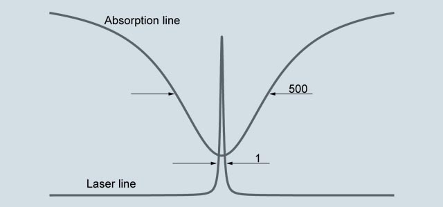
G_PA10_XX_00091
Typical spectral bandwidth of an absorption line compared to the bandwidth of the laser light.
Influences on the measurement
Dust load
As long as the laser beam is able to generate a suitable detector signal, the dust load of the process gases does not influence the analytical result. By applying a dynamic background correction, measurements can be carried out reliably and without any negative impact. Under good conditions, particle densities up to 100 g/Nm3 (distance 1 m) can be handled by the LDS 6. Varying dust loads are compensated by scanning the laser over the gas absorption line and the current background.
The effect of a high dust load is complex and depends on the path length and particle size. The optical damping increases at longer path lengths. Smaller particles also have a very large influence on the optical damping. With a combination of high dust load, long path length and small particle size, the technical support at Siemens should be consulted.
Temperature
The effect of temperature on the absorption strength of the molecular line is compensated by an adjustment factor. An analog temperature signal can be transferred to the device from an external temperature sensor. This signal is then used to correct the influence of the temperature on the observed line strength. If the temperature of the sample gas remains constant, it is alternatively possible to carry out a static correction using a preset value.
At high process gas temperatures, generally from approximately 1 000 °C, there may be noticeable broadband IR radiation of gas and dust, or flames may occasionally occur in the measurement path. An additional optical bandpass filter for an LDS 6 measuring O2 can be set upstream of the detector to protect it and prevent saturation by the strong background radiation.
Pressure
The effect of pressure on the absorption line, and consequently on the measured concentration, is compensated with an adjustment factor. The gas pressure can affect the line shape of the molecular absorption line. An analog pressure signal can be sent to the device from an external pressure sensor to fully compensate for the effect of the pressure including the density effect.
Optical path length
The absorption values analyzed by the LDS 6 are typically small. According to the Lambert-Beer law, the absorption of laser light depends on the optical path length within the gas, among other factors. Therefore, the precision in determining the effective optical path length in the process might limit the overall precision of the measurement.
As the optics on the process side normally need to be purged to keep them clean over a long period of time, the thickness of the mixing zone between the purging medium and the process gas and its concentration distribution need to be considered. In a typical in-situ installation directly in the line and with some meters of path, the influence of the purging gas on the effective path length can be ignored.
Path length and dust load are mutually influencing: the higher the dust load in the process, the shorter the max. possible path length. For short path lengths in the range ≤ 0.3 m, contact Siemens Technical Support.
Maintenance and fault messages
LDS 6 outputs different warnings via relays:
- Need for maintenance (measured value is not influenced)
- Operating error (measured value might be influenced)
Note
Individual requirements for the measuring point can make the utilization of special equipment necessary. The possibilities for adapting the sensors are:
- Different purging media, such as instrument air, ambient air, nitrogen or steam
- Different purging modes on process and optics enclosure sides
- Special materials of purging tubes and/or flanges
- Cooling or heating of the optics enclosure
- Explosion-protected optics enclosure configurations
Essential characteristics
- Integrated calibration adjustment with a built-in reference cell
- Negligible long-term drifts of zero point and span
- Dynamic background correction for varying dust loads
- Isolated signal outputs, 4 to 20 mA
- User-friendly, menu-driven operation
- Selectable time constants (response time)
- Two user levels with individual access codes for prevention of unwanted and unauthorized operations
- Operation according to NAMUR recommendations
- Monitoring of overall optical signal transmission
- Remote preventive maintenance and servicing via Ethernet/modem
- Straightforward replacement of the central unit, since connections can easily be removed
- Optics enclosure and enclosure of central unit free of wear and corrosion
- Easy operation with a numerical keypad and menu prompting
Certified versions for emission monitoring
The LDS 6 is available as certified device for emission monitoring of NH3, NH3/H2O, H2O, HCl, HCl/H2O. The certificates are issued by German Technical Inspectorate for Germany and MCERTS for the United Kingdom. Test kits for ammonia, water and HCl should be used to conduct regular calibration and linearity checks on site. These kits can be ordered separately as device accessories. For new analyzer orders, the NH3, NH3/H2O and H2O kits named "Version 2" must be ordered. For analyzers already installed, contact Siemens Technical Support to determine the correct kit version for your device. Alternatively, this information can be found in the device manual.
Verification of calibration
Assembly with certified, maintenance-free calibration gas cell with connections for laser fiber-optic conductors and detector module of the optics enclosure. These are used to rapidly verify the factory calibration in the field without compressed gas bottles or flow cell.
Calibration verification kits are available for the following sample gases: O2, NH3, CO, CO2, CO/CO2.
P_PA10_XX_00046
Example of an assembly for verification of calibration